U-Boot
Introduction
U-Boot is an open-source bootloader commonly used in embedded devices. It has its origins in a very simple bootloader designed for the PowerPC architecture which was publicly released in 2000 under the name of PPCBoot. Shortly thereafter it was renamed U-Boot (short for Das Universal Boot) to reflect its evolution into a multi architectural bootloader. Today, U-Boot is a fully-fledged bootloader supporting more than a dozen architectures, several filesystems, and a handful of interfaces. It features a console interface through the serial port with low-level commands and environment variables that provide high flexibility when configuring the boot process. The most remarkable achievement, however, is its good driver assortment, which has established it as the preferred bootloader for most embedded platforms. Toradex also uses U-Boot as the bootloader for its images. You can find the code in our repositories.
This article explains how to manage the console and the environment variables in a running U-Boot so that you are able to troubleshoot, modify, or set up your own booting configuration. To learn how to build your own U-Boot version, please refer to Build U-Boot and Linux Kernel from Source Code.
Requirements
In order to access the U-Boot console, you obviously need a running U-Boot in your module. A running U-Boot is automatically available if you have:
- Installed a compatible image from the Linux Software page on our site.
- Used our Toradex Easy Installer to install a compatible image from our feed servers.
- Built your own image from the Toradex Open Embedded meta layers in our git repositories.
The U-Boot Console
When U-Boot is running in RAM, it sends its output through the primary Full Function (FF) UART (usually UART_A). The Colibri and Apalis evaluation boards route this UART through a USB to Serial converter to a USB B connector or through a TTL to RS232 converter to a DB9 connector (see Colibri Evaluation Board, Apalis Evaluation Board). The Iris Board routes this UART through a TTL to RS232 converter to a header (see Serial Adapter Cable on Iris). While U-Boot's console output is also visible on the parallel RGB display (and with the carrier boards RAMDAC on VGA) a USB keyboard directly connected to the module does not work as of yet.
In order to visualize the serial output from a host machine, a serial port reader program such as minicom or PuTTy is commonly set to read the corresponding USB serial port (e.g. in Linux /dev/ttyUSB*). For detailed information on how to set up and configure the serial port on your host machine see our Quickstart Guide.
Once you can read the output from your host machine, the U-Boot Console can be easily accessed by pressing any button before the autoboot sequence starts. By default, U-Boot waits up to 3 seconds before starting the autoboot sequence. The following is an extract of what the console shows when U-Boot is initialized and autoboot is prevented by entering into the console.
U-Boot 2020.04-5.5.0+git.81bc8894031d (Mar 17 2022 - 11:49:00 +0000)

CPU:   NXP i.MX8QXP RevC A35 at 1200 MHz at 45C

DRAM:  2 GiB
MMC:   FSL_SDHC: 0, FSL_SDHC: 1
Loading Environment from MMC... OK
In:    serial
Out:   serial
Err:   serial
Model: Toradex Colibri iMX8 QuadXPlus 2GB Wi-Fi / BT IT V1.0D, Serial# 06995758

 BuildInfo:
  - SCFW 778670e2, SECO-FW 7aeb8423, IMX-MKIMAGE 8947fea3, ATF 835a8f6
  - U-Boot 2020.04-5.5.0+git.81bc8894031d

flash target is MMC:0
Net:   eth0: ethernet@5b040000 [PRIME]
Fastboot: Normal
Normal Boot
Hit any key to stop autoboot:  0
Colibri iMX8X #
U-Boot Variables
Environment Variables
Environment variables are key-value pairs of strings that are used by U-Boot as configuration or to execute commands. The following table lists the most important environment variables and their default values:
| Environment Variable | Description | Default Value | Allowed Value |
|---|---|---|---|
| baudrate | Debug console baud rate | 115200 | Supported baudrate for the specific SoM |
| boot_devnum | Boot device number | ${devnum} | 0 .. MAX_DEV_NUM |
| boot_targets or boot_devtype | Boot device type | ${devtype} | mmc, usb, tftp, dhcp |
| boot_part | Boot partition number | ${distro_bootpart} | 1 .. MAX_PART_NUM |
| console | Debug console port | SoM dependant | SoM dependant (e.g. “ttymxc0" for colibri-imx7) |
| fdtfile | Store device tree filename | SoM dependant | String with any device tree binary in boot partition In other words, any file *.dtb (e.g. imx8qxp-colibri-eval-v3.dtb) |
| fdt_board | Set carrier board | Apalis: “eval" Colibri: “eval-v3" Verdin: “dev" | Carrier Board dependant (e.g. "aster", "eval", ...) |
| kernel_image | Set kernel name on boot partition | zImage or Image.gz | String |
| overlays_file | Store overlays text-file's name | "overlays.txt" | String |
| overlays_prefix | Store where overlays_file is stored | "Overlays/" | String |
| rootfsargs | Set kernel parameters of where the kernel finds the rootfs | Depends on root_devtype | String with Kernel parameters |
| root_devnum | Rootfs device number | ${devnum} | 0 .. MAX_DEV_NUM |
| root_devtype | Rootfs device type | ${devtype} | mmc, usb, nfs-dhcp, nfs-static |
| root_part | Rootfs partition number | 2 | 1 .. MAX_PART_NUM |
| skip_fdt_overlays | Set to skip loading devide tree overlays | empty, “0", “1" | |
| tdxargs | Set extra kernel parameters | String with Kernel parameters |
The variable fdt_file, used for storing device tree name, is now deprecated and was replaced by fdtfile. Should no longer be used since the full adoption of distroboot.
To list all currently set variables, issue the command printenv in the U-Boot console.
> printenv
altbootcmd=env set rollback 1; run bootcmd
arch=arm
baudrate=115200
board=colibri-imx8x
board_name=Colibri iMX8QXP
board_rev=v1.0
...
boot_targets=mmc1 mmc0 usb0 dhcp
..
fdt_board=eval-v3
fdtcontroladdr=fd66f558
fdtfile=imx8qxp-colibri-eval-v3.dtb
..
image=Image
...
preboot=setenv fdtfile ${soc}-colibri-${fdt_board}.dtb
ramdisk_addr_r=0x8a000000
rootpath=/srv/nfs
...
Some variables, such as arch or vidargs contain information needed for configuration. Others such as scan_dev_for_boot and bootcmd also contain commands (run, echo, etc) that can be run.
> printenv
...
vidargs=video=imxdpufb5:off video=imxdpufb6:off video=imxdpufb7:off
...
scan_dev_for_boot=echo Scanning ${devtype} ${devnum}:${distro_bootpart}...; for prefix in ${boot_prefixes}; do run scan_dev_for_extlinux; run scan_dev_for_scripts; done;
scan_dev_for_boot_part=part list ${devtype} ${devnum} -bootable devplist; env exists devplist || setenv devplist 1; for distro_bootpart in ${devplist}; do if fstype ${devtype} ${devnum}:${distro_bootpart} bootfstype; then run scan_dev_for_boot; fi; done; setenv devplist
...
bootcmd=run bootcmd_mmc0
To print the value of a single variable, use printenv <variable>.
> printenv fdt_board
fdt_board=eval-v3
Colibri iMX8X # printenv boot_targets
boot_targets=mmc1 mmc0 usb0 dhcp
Device Tree Filename (fdtfile)
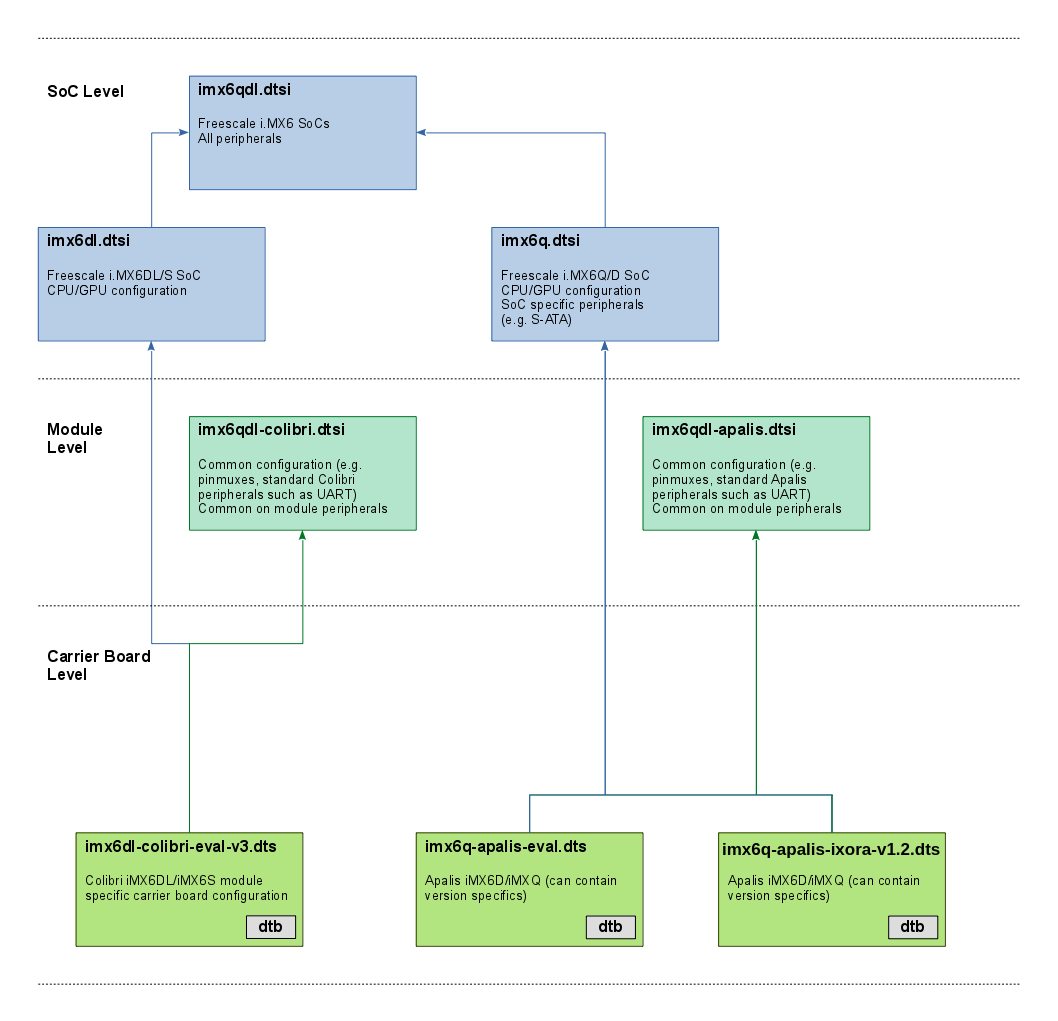
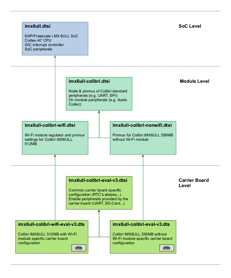
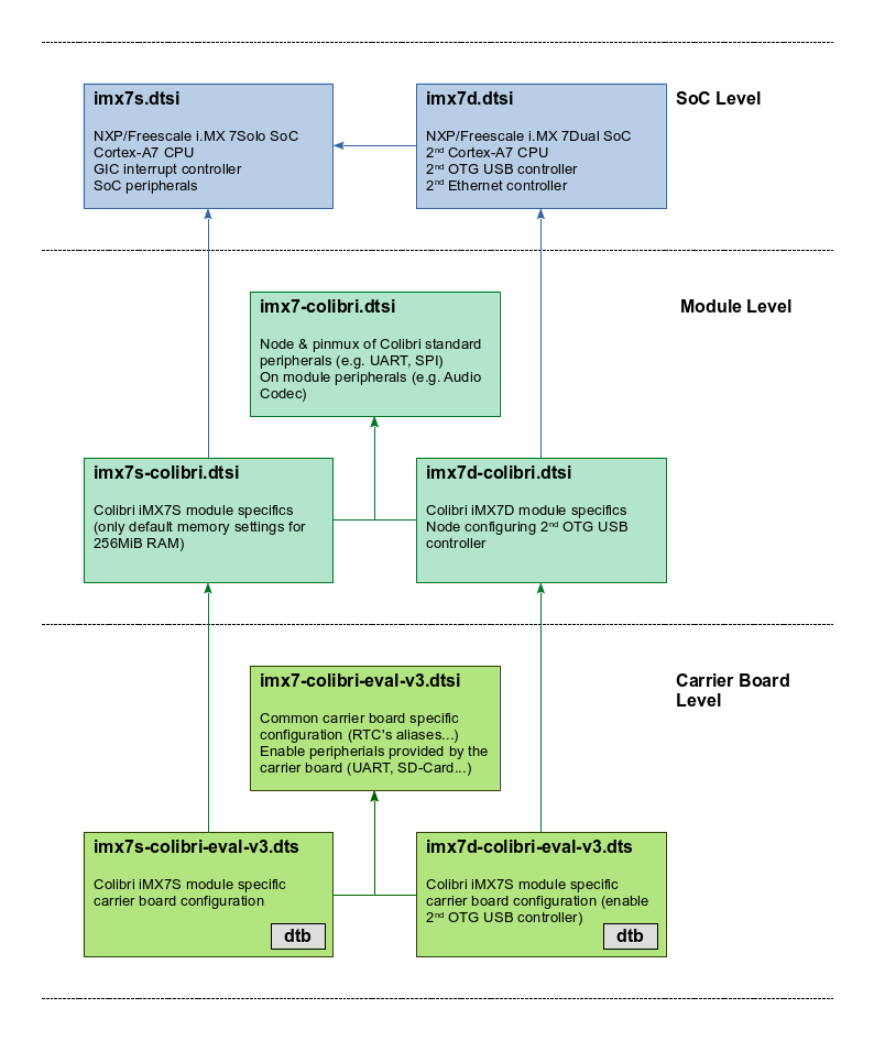
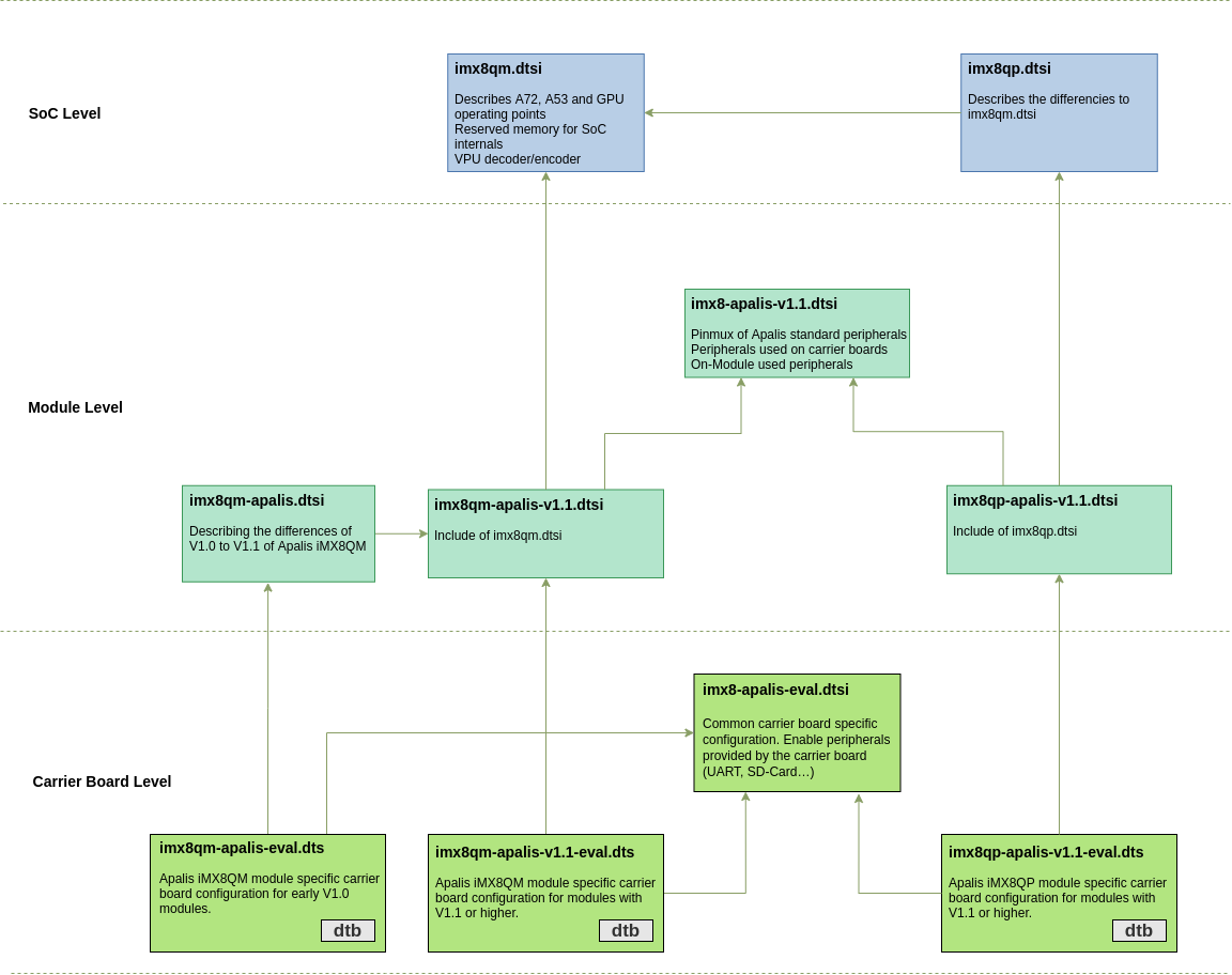
To update (or modify) the fdtfile variable, you can use one of the supported device trees shown in the diagram below, or create your own.
To read more about Device Trees, refer to Device Tree Customization article.
You can refer to this hierarchy to get a better understanding about the dependency between parent and children device trees in our BSP.
- i.MX 6 Based Modules
- i.MX 6ULL Based Modules
- i.MX 7 Based Modules
- i.MX 8 Family Based Modules
- i.MX 8X Based Modules
- i.MX 8M Mini Based Modules
- Vybrid Based Modules
i.MX 6 Based Modules
The modules Colibri iMX6S/iMX6DL share the same device tree binary, so do the modules Apalis iMX6D/iMX6Q. Click on the box to see the current version of the respective device tree file.
Pinmux (iMX6)
Pin configuration such as pinmux or drive strength is either set by pinctrl-imx6dl or the pinctrl-imx6q driver. The SoC level device trees define the base configuration and allow to extend entries through the iomuxc label.
To configure a pin, a device tree node inside the pin controller node with the property fsl,pins is required. Cells need to be assigned to the property, each pin requires 5 cells. However, the first four are usually given by a pre-processor macro (see arch/arm/boot/dts/imx6dl-pinfunc.h or imx6q-pinfunc.h respectively). The macros consist of three parts, a prefix, the pad (or ball) name (as used in datasheets) and the alternate function name. Since each pad has multiple alternate functions, there are multiple macros for a single pad, all ending with a different alternate function. It is crucial to select the correct macro for the intended use (e.g. the macro which contains GPIO as an alternate function if the pad is going to be used as a GPIO).
MX6QDL_PAD_EIM_A24__GPIO5_IO04

Prefix: MX6QDL_PAD
Pad/ball name: EIM_A24
Alternate function: GPIO5_IO04
The 5th and last cell of a pin muxing entry need to be provided as a number in the device tree. This last cell contains the pin settings typically in a hexadecimal notation. Additionally, the last cell's bit 30 is used to give the setting of the SION bit, bit 31 prevents the iomuxc from changing the pad control register (see here for details).
pinctrl_additionalgpio: additionalgpios {
    fsl,pins = <
        MX6QDL_PAD_EIM_A24__GPIO5_IO04      0x1b0b0
    >;
};
There are preprocessor define for commonly used default pin configurations (e.g. PAD_CTRL_HYS_PU).
The bitwise definition for the last cell is given by the registers of the i.MX 6 Input/Output Multiplexer Controller.
| Bit(s) | Field | Description | Remarks |
|---|---|---|---|
| 16 | HYS | 0 - CMOS input 1 - Schmitt trigger input | |
| 15-14 | PUS | 00 - 100 kOhm Pull Down 01 - 47 kOhm Pull Up 10 - 100 kOhm Pull Up 11 - 22 kOhm Pull Up | |
| 13 | PUE | 0 - Keeper enable 1 - Pull enable | Selection between keeper and pull up/down function |
| 12 | PKE | 0 - Pull/Keeper Disabled 1 - Pull/Keeper Enabled Enable | enable keeper or pull up/down function |
| 11 | ODE | 0 - Output is CMOS 1 - Output is open drain | |
| 7-6 | SPEED | 00 - Low (50 MHz) 01 - Medium (100,150 MHz) 10 - Medium (100,150 MHz) 11 - High (100,150,200 MHz) | |
| 5-3 | DSE | 000 - output driver disabled (Hi Z) 001 - 150 Ohm (240 Ohm if pad is DDR) 010 - 75 Ohm (120 Ohm if pad is DDR) 011 - 50 Ohm (80 Ohm if pad is DDR) 100 - 37 Ohm 60 hm if pad is DDR) 101 - 30 Ohm (48 Ohm if pad is DDR) 110 - 25 Ohm 111 - 20 Ohm (34 Ohm if pad is DDR) | |
| 0 | SRE | 0 - Slow Slew Rate 1 - Fast Slew Rate |
For further details see Chapter 4 of the Toradex Colibri or Apalis iMX6 datasheet or/and Chapter 36 of the NXP®/Freescale i.MX 6 application processor reference manual.
i.MX 6ULL Based Modules
Both versions of the Colibri iMX6ULL modules (256MB without Wi-Fi and 512MB with Wi-Fi) share the same SoC-level device tree file (imx6ull.dtsi) and there are dedicated files to each module.
Pinmux (iMX6ULL)
The i.MX 6ULL SoC allows multiplexing pins through its Input/Output Multiplexer Controller (IOMUXC). Beside multiplexing pins, this controller allows also to set pin configuration such drive strength. There are two largely independent controllers: the IOMUXC and the IOMUXC LPSR (low-power pin controller). The SoC level device trees define the driver node for each of this controller which bind to the pinctrl-imx6ul driver and defines the labels iomuxc and iomuxc_lpsr to give lower-level device tree access to the node.
To configure a pin, a device tree node inside the pin controller node with the property fsl,pins is required. Cells need to be assigned to the property, each pin requires 5 cells. However, the first four are usually given by a pre-processor macro (see arch/arm/boot/dts/imx6ull-pinfunc.h or arch/arm/boot/dts/imx6ull-pinfunc-lpsr.h respectively), only the last cell need to be provided. This last cell contains the pin settings in a hexadecimal notation. Additionally, the last cell's bit 30 is used to give the setting of the SION bit, bit 31 prevents the iomuxc from changing the pad control register (see here for details). Since i.MX 6ULL SoC shares pin assignments with the i.MX 6UL SoC, various pin assignments for both processors are in the file arch/arm/boot/dts/imx6ul-pinfunc.h, which is included to arch/arm/boot/dts/imx6ull-pinfunc.h.
&iomuxc {
...
    pinctrl_can_int: canintgrp {
        fsl,pins = <
            MX6UL_PAD_ENET1_TX_DATA1__GPIO2_IO04    0x13010 /* SODIMM 73 */
        >;
    };
...
};
The bitwise definition for the last cell is given by the PAD Control Registers of the i.MX 6ULL Input/Output Multiplexer Controller.
| Bit(s) | Field | Description | Remarks |
|---|---|---|---|
| 16 | HYS | 0 - CMOS input 1 - Schmitt trigger input | |
| 15-14 | PUS | 00 - 100 kOhm Pull Down 01 - 47 kOhm Pull Up 10 - 100 kOhm Pull Up 11 - 22 kOhm Pull Up | |
| 13 | PUE | 0 - Keeper enable 1 - Pull enable | Selection between keeper and pull up/down function |
| 12 | PKE | 0 - Pull/Keeper Disabled 1 - Pull/Keeper Enabled Enable | Enable keeper or pull up/down function |
| 11 | ODE | 0 - Output is CMOS 1 - Output is open drain | |
| 7-6 | SPEED | 00 - Low (50 MHz) 01 - Medium (100,150 MHz) 10 - Medium (100,150 MHz) 11 - High (100,150,200 MHz) | |
| 5-3 | DSE | 000 - output driver disabled (Hi Z) 001 - 260 ohm 010 - 130 ohm 011 - 87 ohm 100 - 65 ohm 101 - 52 ohm 110 - 43 ohm 111 - 37 ohm | |
| 0 | SRE | 0 - Slow Slew Rate 1 - Fast Slew Rate |
For further details see Chapter 4 of the Toradex Colibri iMX6ULL datasheet or/and Chapters 4 and 32 of the NXP®/Freescale i.MX 6ULL application processor reference manual.
i.MX 7 Based Modules
The modules Colibri iMX7S/iMX7D use independent device tree binaries, but due to the high intersection, most of the logic is in shared device tree source files.
Pinmux (iMX7)
The i.MX 7 SoC allows multiplexing pins through its Input/Output Multiplexer Controller (IOMUXC). Beside multiplexing pins, this controller allows also to set pin configuration such drive strength. There are two largely independent controllers: the IOMUXC and the IOMUXC LPSR (low-power pin controller). The SoC level device trees define the driver node for each of this controller which bind to the pinctrl-imx7 driver and defines the labels iomuxc and iomuxc_lpsr to give lower-level device tree access to the node.
To configure a pin, a device tree node inside the pin controller node with the property fsl, pins is required. Cells need to be assigned to the property, each pin requires 5 cells. However, the first four are usually given by a pre-processor macro (see arch/arm/boot/dts/imx7d-pinfunc.h or arch/arm/boot/dts/imx7d-pinfunc-lpsr.h respectively), only the last cell need to be provided. This last cell contains the pin settings in a hexadecimal notation. Additionally, the last cell's bit 30 is used to give the setting of the SION bit, bit 31 prevents the iomuxc from changing the pad control register (see here for details).
&iomuxc {
...
    pinctrl_can_int: canintgrp {
        fsl,pins = <
            MX7D_PAD_SD1_RESET_B__GPIO5_IO2     0x14 /* SODIMM 73 */
        >;
    };
...
};
The bitwise definition for the last cell is given by the PAD Control Registers of the i.MX 7 Input/Output Multiplexer Controller.
| Bit(s) | Field | Description | Remarks |
|---|---|---|---|
| 6-5 | PS | 00 - 100 kOhm Pull Down 01 - 5 kOhm Pull Up 10 - 47 kOhm Pull Up 11 - 100 kOhm Pull Up | |
| 4 | PE | 0 - Pull disable 1 - Pull enable | Pull Enable field |
| 3 | HYS | 0 - Hysteresis Disabled 1 - Hysteresis Enabled | |
| 2 | SRE | 0 - Fast Slew Rate 1 - Slow Slew Rate | |
| 1-0 | DSE | 00 - X1 01 - X4 10 - X2 11 - X6 | Drive Strength Field |
For further details see Chapter 4 of the Toradex Colibri iMX7 datasheet or/and Chapter 8 of the NXP®/Freescale i.MX 7 application processor reference manual.
i.MX 8 Family Based Modules
Pinmux (i.MX 8 Family Based Modules)
The i.MX 8 family SoCs allow multiplexing pins through its Input/Output Multiplexer Controller (IOMUXD). Beside multiplexing pins, this controller allows setting pin configuration such as drive strength. The SoC level device trees define the driver node for this controller.
All pinmuxing/drive strength etc. is controlled in the System Controller Unit, a dedicated M-Core running the System Controller Firmware (SCFW). Linux's IOMUXC driver has no direct access to IOMUXC registers but uses the SCU driver to communicate with its firmware (SCFW).
To configure a pin, a device tree node inside the pin controller node with the property fsl,pins is required. Integers need to be assigned to the property, each pin requires 3 integers. However, the first two are usually given by a #define (see include/dt-bindings/pinctrl/pads-imx8qm.h). With this define the SoC pin and its desired function is specified. In the example down below for example the pin FLEXCAN0_TX is muxed to the function DMA_FLEXCAN0_TX.
The third integer then defines the pin settings in hexadecimal notation. On the example below 0x21 means that Bit 0 and Bit 5 is set. Bit 0 sets high or low drive strength in this example with 1 meaning low drive strength. With Bit 6-5 the pull-up or pull-down behaviour is controlled with '01' meaning pull-up.
For a detailed description and table of possible pin-settings, look them up in the Reference Manual for the i.MX 8 family. At the time of writing this, the chapter for FLEXCAN0_TX pin settings was located at chapter 9.2.5.1.160.4
The possible muxings can be found in chapter 4 in the datasheet or with our Pinout Designer pinout.torizon.io.
The meaning of these bits depends on the pin and has to be looked up for every pin in the Reference Manual. Thus we can not give a table here.
&iomuxc {
...
        apalis-imx8qm {
                pinctrl_flexcan1: flexcan0grp {
                        fsl,pins = <
                                IMX8QM_FLEXCAN0_TX_DMA_FLEXCAN0_TX              0x21
                                IMX8QM_FLEXCAN0_RX_DMA_FLEXCAN0_RX              0x21
                        >;
                };
        };
...
};
i.MX 8X Based Modules
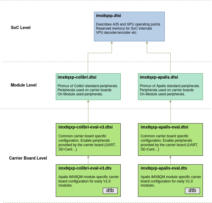
Pinmux (i.MX 8X Based modules)
The i.MX 8X SoC allows multiplexing pins through its Input/Output Multiplexer Controller (IOMUXD). Beside multiplexing pins, this controller allows setting pin configuration such as drive strength. The SoC level device trees define the driver node for this controller.
All pinmuxing/drive strength etc. is controlled in the System Controller Unit, a dedicated M-Core running the System Controller Firmware (SCFW). Linux's IOMUXC driver has no direct access to IOMUXC registers but uses the SCU driver to communicate with its firmware (SCFW).
To configure a pin, a device tree node inside the pin controller node with the property fsl,pins is required. Integers need to be assigned to the property, each pin requires 3 integers. However, the first two are usually given by a #define (see include/dt-bindings/pinctrl/pads-imx8qxp.h). With this define the SoC pin and its desired function is specified. In the example down below for example the pin FLEXCAN0_TX is muxed to the function DMA_FLEXCAN0_TX.
The third integer then defines the pin settings in hexadecimal notation. On the example below 0x21 means that Bit 0 and Bit 5 is set. Bit 0 sets high or low drive strength in this example with 1 meaning low drive strength. With Bit 6-5 the pull-up or pull-down behaviour is controlled with '01' meaning pull-up.
For a detailed description and table of possible pin-settings, look them up in the Reference Manual for i.MX 8X. At the time of writing this, the chapter for FLEXCAN0_TX pin settings was located at chapter 9.2.5.1.115.4.
The possible muxings can be found in chapter 4 in the datasheet or with our Pinout Designer pinout.torizon.io.
The meaning of these bits depends on the pin and has to be looked up for every pin in the Reference Manual. Thus we can not give a table here.
&iomuxc {
...
        colibri-imx8qxp {
                pinctrl_flexcan1: flexcan0grp {
                        fsl,pins = <
                                IMX8QXP_FLEXCAN0_TX_ADMA_FLEXCAN0_TX            0x21
                                IMX8QXP_FLEXCAN0_RX_ADMA_FLEXCAN0_RX            0x21
                        >;
                };
        };
...
};
i.MX 8M Mini Based Modules
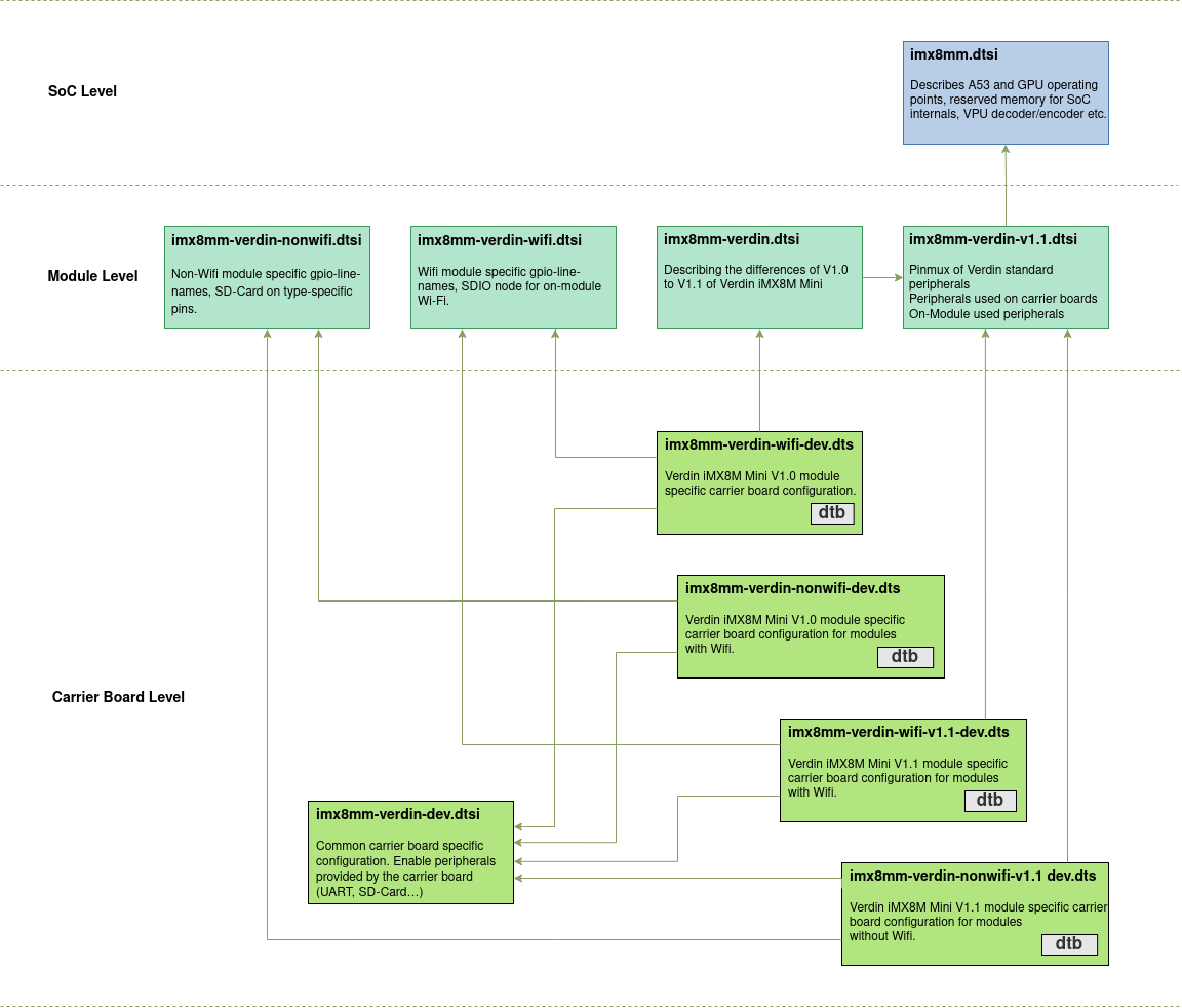
Pinmux (i.MX 8M Mini Based modules)
The i.MX 8M Mini SoC allows multiplexing pins through its Input/Output Multiplexer Controller (IOMUXD). Beside multiplexing pins, this controller allows setting pin configuration such as drive strength.
To configure a pin, a device tree node inside the pin controller node with the property fsl,pins is required. Integers need to be assigned to the property, each pin requires 6 integers. However, the first 5 are usually given by a #define (see arch/arm64/boot/dts/freescale/imx8mm-pinfunc.h). With this define the SoC pin and its desired function is specified. In the example down below, for example, the pin GPIO1_IO06 is muxed to the function GPIO1_IO06 (Which is pretty obvious but GPIO1_IO06 could also be muxed to USDHC1_CD_B with the define MX8MM_IOMUXC_GPIO1_IO06_USDHC1_CD_B for example).
The third integer then defines the pin settings in hexadecimal notation. On the example below 0x1c4 means that Bit 2, 6, 7 and Bit 8 are set. With Bit 0-2 one can set the drive strength. In this example, only Bit 2 is set which is meaning drive strength X2. Bit 6 means "Select pull-up resistors", Bit 7 "Select Schmitt input" and Bit 8 "Enable pull resistors".
For a detailed description and table of possible pin-settings, look them up in the Reference Manual. At the time of writing this, the chapter for PAD_GPIO1_IO06 pin settings was located at chapter 8.2.5.166.
The possible muxings can be found in chapter 4 in the datasheet or with our Pinout Designer pinout.torizon.io.
&iomuxc {
...
        pinctrl_can1_int: can1intgrp {
                fsl,pins = <
                        MX8MM_IOMUXC_GPIO1_IO06_GPIO1_IO6        0x1c4
                >;
        };
...
};
Vybrid Based Modules
The device tree files for the Colibri VF50/VF61 modules are quite similar, hence the common device tree nodes have been factored out to vf-colibri.dtsi and vf-colibri-eval-v3.dtsi. Click on the box to see the current version of the respective device tree file.
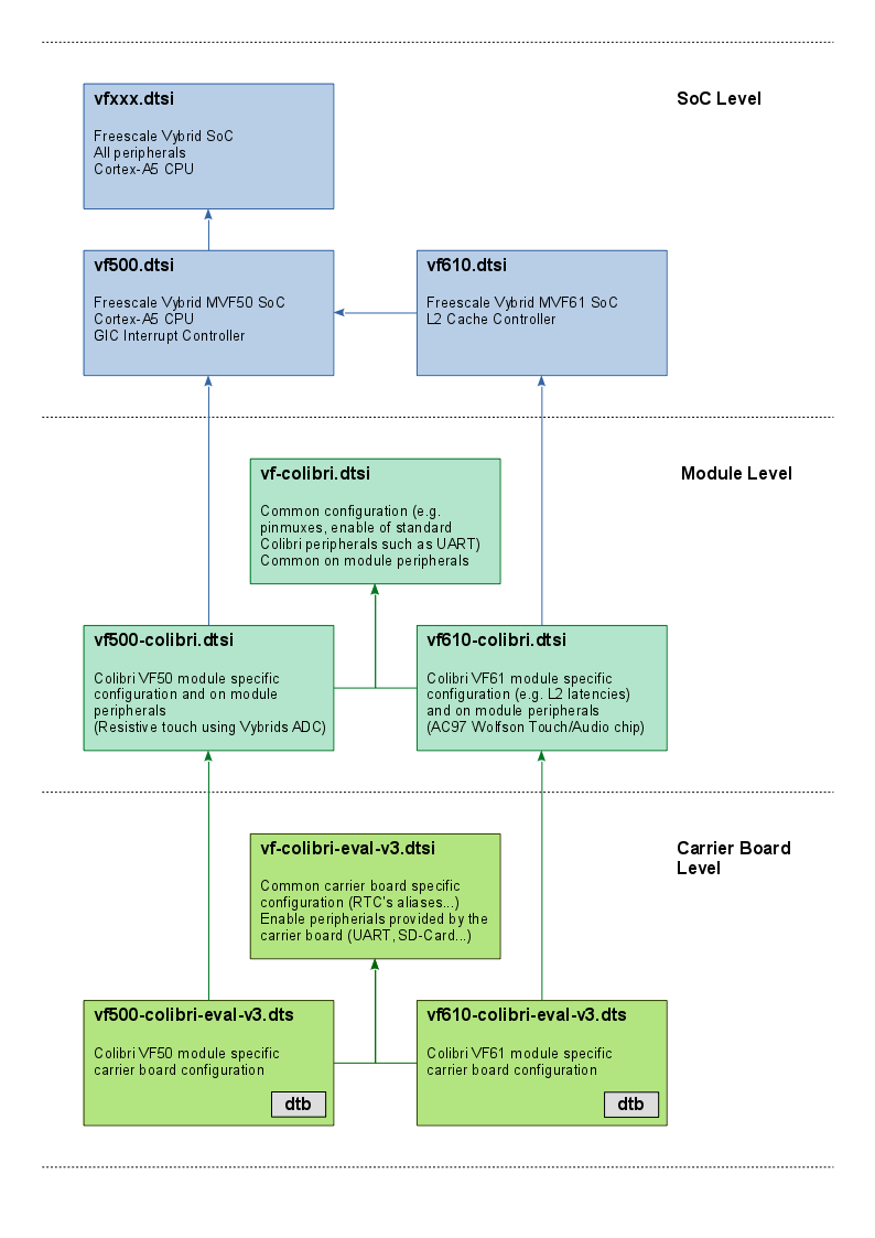
A device tree for a custom carrier board can also implement this extra dtsi for the common nodes between Colibri VF50/VF61. If the carrier board will only use Colibri VF50 or only Colibri VF61 anyway, the nodes of the common device tree file (vf-colibri-eval-v3.dtsi) can also be included in the main carrier board device tree (e.g. vf500-colibri-eval-v3.dts).
The Vybrid default boot scripts in U-Boot load the device tree file by combining multiple environment variables: ${soc}-colibri-${fdt_board}.dtb. The soc environment variable is detected according to the module type the boot loader runs on (vf500/vf610). The fdt_board is a static environment variable set to eval-v3 by default. If you provide your own carrier board device tree, you can make use of this environment variable to select the correct device tree:
setenv fdt_board mycarrier
saveenv
Pinmux (Vybrid)
Pin configurations such as pinmux or drive strength settings are defined by the pinctrl-vf610 driver. The base device tree vfxxx.dtsi defines the base configuration and allows these entries to be extended through the iomuxc label.
To configure a pin, a device tree node inside the pin controller node with the property fsl,pins is required. Cells need to be assigned to the property, each pin requires 5 cells. However, the first four are usually given by a pre-processor macro (see arch/arm/boot/dts/vf610-pinfunc.h), only the last cell needs to be provided. This last cell contains the pin settings in a hexadecimal notation.
pinctrl_additionalgpio: additionalgpios {
    fsl,pins = <
        VF610_PAD_PTA17__GPIO_7     0x22ed
    >;
};
The bitwise definition for the last cell is given by the registers of Vybrids Input/Output Multiplexer Controller. Refer to the following table for their meaning:
| Bit(s) | Field | Description | Remarks |
|---|---|---|---|
| 13-12 | SPEED | 00 - Low (50 MHz) 01 - Medium (100 MHz) 10 - Medium (100 MHz) 11 - High (200 MHz) | |
| 11 | SRE | 0 - Slow Slew Rate 1 - Fast Slew Rate | |
| 10 | ODE | 0 - Output is CMOS 1 - Output is open drain | |
| 9 | HYS | 0 - CMOS input 1 - Schmitt trigger input | |
| 8-6 | DSE | 000 - output driver disabled 001 - 150 Ohm (240 Ohm if pad is DDR) 010 - 75 Ohm (120 Ohm if pad is DDR) 011 - 50 Ohm (80 Ohm if pad is DDR) 100 - 37 Ohm 60 hm if pad is DDR) 101 - 30 Ohm (48 Ohm if pad is DDR) 110 - 25 Ohm 111 - 20 Ohm (34 Ohm if pad is DDR) | |
| 5-4 | PUS | 00 - 100 kOhm Pull Down 01 - 47 kOhm Pull Up 10 - 100 kOhm Pull Up 11 - 22 kOhm Pull Up | |
| 3 | PKE | 0 - Pull/Keeper Disabled 1 - Pull/Keeper Enabled Enable | enable keeper or pull up/down function |
| 2 | PUE | 0 - Keeper enable 1 - Pull enable | Selection between keeper and pull up/down function |
| 1 | OBE | 0 - Output buffer disabled 1 - Output buffer enabled | |
| 0 | IBE | 0 - Input buffer disabled 1 - Input buffer enabled |
For further details see Chapter 4.2 of the Colibri VFxx datasheet or/and Chapter 6 of the NXP®/Freescale Vybrid reference manual.
GPIO (Vybrid)
On Vybrid almost all pins can be used as a GPIO. To be able to use a pin as a GPIO, a valid GPIO pinmux must be present in the device tree. Our default device tree contains such a pinmux entry for all pins which are defined as being a GPIO by default (refer to the datasheet). For the other pins, make sure no driver is requesting them and create a proper pinmux configuration according to the Pinmux chapter.
There are 5 GPIO ports on Vybrid, represented by the node references gpio0 through gpio4. Each of which can address up to 32 GPIOs. Which GPIO port is used is defined by the GPIO node reference, the GPIO number within the port is the first cell. The assignment of the to Colibri pins to the GPIO blocks/numbers can be found in the Colibri VFxx Datasheet, Chapter 4.4 List Functions, GPIO port column. The GPIO polarity cell needs to be chosen according to the drivers/electronics needs. There are also preprocessor macros which can be used instead of the numbers (GPIO_ACTIVE_HIGH/GPIO_ACTIVE_LOW).
E.g. to reference the pin Colibri SO-DIMM 133 (according to the Colibri VFxx Datasheet connected to Vybrids PORT2[24]) one needs to use this GPIO specification:
gpios = <&gpio2 24 GPIO_ACTIVE_HIGH>
Vybrid starts counting its GPIO banks with 0, hence the first bank is available under the label gpio0.
User-space
To use a SO-DIMM as GPIO using the sysfs interface (see GPIO (Linux)), a valid pinmux configuration is required. Most GPIOs have a valid configuration in the vf-colibri.dtsi device tree under the node additionalgpios.
If there is no pinmux for the pin in question, the sysfs layer will respond with a "Invalid argument" error:
# echo 0 > /sys/class/gpio/export
-sh: echo: write error: Invalid argument
In this case, add a Pinmux entry as described above.
In case the pin is already in use by a different driver, the error code would be "Device or resource busy".
# echo 42 > /sys/class/gpio/export
-sh: echo: write error: Device or resource busy
Make sure the SO-DIMM pin in question is not in use by any driver. In case a driver is referencing it, you can disable the driver.
To update/change the value of the variable fdtfile, as further explained on the section Creating and Modifying Variables, you can either set a new device tree on fdtfile, or set a different board at fdt_board. For example:
> printenv fdt_board
fdt_board=dev
> printenv fdtfile
fdtfile=imx8mp-verdin-wifi-dev.dtb
> setenv fdt_board dahlia
> saveenv
> boot
However, this expected behavior does not work on BSP 6.x.y, as you can see on the output below.
U-Boot 2022.04-6.1.0-devel+git.944a4ccb70e4 (Nov 08 2022 - 11:29:12 +0000)

CPU:   i.MX8MP[8] rev1.1 1600 MHz (running at 1200 MHz)
CPU:   Industrial temperature grade (-40C to 105C) at 56C
Reset cause: POR
DRAM:  4 GiB
Core:  89 devices, 23 uclasses, devicetree: separate
WDT:   Started watchdog@30280000 with servicing (60s timeout)
MMC:   FSL_SDHC: 1, FSL_SDHC: 2
Loading Environment from MMC... OK
In:    serial@30880000
Out:   serial@30880000
Err:   serial@30880000
Model: Toradex 0058 Verdin iMX8M Plus Quad 4GB WB IT V1.0D
Serial#: 07174398
Carrier: Toradex Dahlia V1.1C, Serial# 10952631
Net:   eth1: ethernet@30be0000, eth0: ethernet@30bf0000 [PRIME]
Normal Boot
Hit any key to stop autoboot:  0
Verdin iMX8MP # printenv fdt_board
fdt_board=dahlia
Verdin iMX8MP # printenv fdtfile
fdtfile=imx8mp-verdin-wifi-dev.dtb
The situation happens because the fdtfile variable is automatically set by the preboot u-boot script, so if the fdtfile variable is already setup on the saved environment, the preboot script will not touch it. Then, if you want to use the fdt_board mechanism to change the carrier board, delete the fdtfile before saving the environment so that the override is not present upon boot:
> setenv fdtfile
> setenv fdt_board dahlia
> saveenv
And your output result should be something like:
U-Boot 2022.04-6.1.0-devel+git.944a4ccb70e4 (Nov 08 2022 - 11:29:12 +0000)

CPU:   i.MX8MP[8] rev1.1 1600 MHz (running at 1200 MHz)
CPU:   Industrial temperature grade (-40C to 105C) at 56C
Reset cause: POR
DRAM:  4 GiB
Core:  89 devices, 23 uclasses, devicetree: separate
WDT:   Started watchdog@30280000 with servicing (60s timeout)
MMC:   FSL_SDHC: 1, FSL_SDHC: 2
Loading Environment from MMC... OK
In:    serial@30880000
Out:   serial@30880000
Err:   serial@30880000
Model: Toradex 0058 Verdin iMX8M Plus Quad 4GB WB IT V1.0D
Serial#: 07174398
Carrier: Toradex Dahlia V1.1C, Serial# 10952631
Net:   eth1: ethernet@30be0000, eth0: ethernet@30bf0000 [PRIME]
Normal Boot
Hit any key to stop autoboot:  0
Verdin iMX8MP # printenv fdt_board
fdt_board=dahlia
Verdin iMX8MP # printenv fdtfile
fdtfile=imx8mp-verdin-wifi-dahlia.dtb
Distroboot Variables
Distro Boot is an informal name that refers to the Generic Distro Configuration Concept that U-Boot developers came up with around 2014. When Distro Boot is enabled in U-Boot, you can boot any supported distribution for your platform simply by placing an image in a conveniently partitioned removable device with the corresponding boot configuration file. The Distro Boot article describes the procedure to boot images through the Distro Boot mechanism.
This list contains only variables used in the boot script.
| Variable | Description |
|---|---|
| boot_targets | The list of boot locations searched. Example: mmc0, mmc1, sd, usb |
| devnum | Variable set by distro-boot to the current device-number Note: In our boot script we also use boot_devnum |
| devtype | Variable set by distro-boot to the current device Note: In our boot script we also use boot_devtype |
Internal Variables
When it comes to internal variables, use Read Only.
| Variable | Description |
|---|---|
| bootargs | Aggregate boot arguments. Use instead one of defargs, rootfsargs, setupargs, vidargs, tdxargs |
| bootcmd_boot | Script storage - used to store a script for the actual boot-process |
| bootcmd_dtb | Script storage - used to store the script for device tree loading |
| bootcmd_kernel | Script storage - used to store the script for kernel loading |
| bootcmd_unzip | Script storage- used to store the script for unzipping the kernel on i.MX8 based SoMs |
| defargs | Used by Toradex to set platform specific kernel arguments on compile-time. |
| fdt_addr_r | Set by Toradex - Contains a memory address where the device tree gets loaded to |
| fdt_high | Set by Toradex - Contains a memory address where the device tree gets relocated |
| fdt_overlays | Aggregated values - used to store overlays that are loaded |
| filesize | Set by U-Boot - Contains the filesize in hex this gets set. e.g. after loading a file into memory with load mmc 0 ${loadaddr} zImage |
| fitconf_fdt_overlays | Aggregated values - used to store overlays from overlays.txt |
| kernel_addr_load | Variable set by boot script to store where the kernel should be loaded to in memory |
| kernel_addr_r | Set by Toradex - Contains a memory address where the kernel gets loaded to |
| load_cmd | Script storage |
| load_overlays_file | Script storage |
| loadaddr | Set by Toradex - Contains a memory address where data can be store to |
| overlay_file | Used to buffer the current overlay to be loaded in a for loop in our boot script |
| ramdisk_addr_r | Set by Toradex - Contains a memory address where an initial ramdisk will be loaded |
| rootfsargs_set | Stores the kernel parameters where to find rootfs. This is set within the boot script use rootfsargs if you want to change it. |
| setupargs | Used by Toradex to set platform specific kernel arguments. Difference to defargs is that this variable is dynamically composed by running run setup shortly before boot. |
| set_apply_overlays | Script storage for Toradex boot script |
| set_bootcmd_dtb | Script storage for Toradex boot script |
| set_bootcmd_kernel | Script storage for Toradex boot script |
| set_load_overlays_file | Script storage for Toradex boot script |
| soc | Is set by Uboot and used by us on some platforms to set fdtfile |
| variant | Platforms that need different device trees for nonwifi and wifi SKUs this variable is used to select the correct device tree. Note: On some modules this variable is also used to set SoM version if needed (e.g “-wifi-v1.1", “-emmc"). Note: This variable is set every boot. |
Creating and Modifying Variables
One of the most important things is to know how to set or modify a variable value. Setting a value for an existing variable is done using the command setenv <variable> <value>.
Colibri iMX8X # printenv fdt_board
fdt_board=eval-v3
Colibri iMX8X # setenv fdt_board aster
Colibri iMX8X # printenv fdt_board
fdt_board=aster
In the previous example, you can see that the variable fdt_board contains the default string "eval-v3", which was modified to "aster" using the setenv command.
Either way, you can create a new variable using the command setenv and, following the same process as explained before, add and change its value.
Colibri iMX8X # setenv myvar myvalue
Colibri iMX8X # printenv myvar
myvar=myvalue
Also, you can expand the value of a variable inside the definition of another variable by prepending $ to it.
Colibri iMX8X # setenv myvar2 $myvar
Colibri iMX8X # printenv myvar2
myvar2=myvalue
You must enclose the value of the variable with ' ' if you don't want to expand other variables or if multiple statements are given.
Colibri iMX8X # setenv defargs 'video=tegrafb vmalloc=248M usb_high_speed=1'
When it comes to BSP 5 or later versions, all custom kernel parameters must be modified under the environment variable tdxargs. If not done this way, the changes will not work. A complete list of all custom kernel parameters is at the following link: The kernel’s command-line parameters.
Changing an existing variable, as mentioned before, requires the use of setenv. On the other side, changing some of those environment parameters may require the definition inside the definition of internal variables (as you can see in the description in the table above) or, incase of kernel parameters, tdxargs.The following variables are appended at the end of bootcmd_args and are used when the system is booted:
defargsrootfsargssetupargsvidargstdxargs
For example, to override the content of the variable console as well as the baudrate, you have to define console and baudrate inside setupargs, like the following example:
# env set setupargs "console=${console},${baudrate} console=tty1 consoleblank=0"
Overriding the console and the console baud rate might imply an unexpected result since you end up with U-Boot and Linux sharing different ports or using the UART but with a different baud rate.
Saving the Environment
Using setenv to create or modify variables will only add or change their values in RAM. If you want to make changes permanent they need to be stored in flash with the saveenv command:
Colibri iMX8X # setenv myvar myvalue
Colibri iMX8X # saveenv
Saving Environment to MMC...
Writing to MMC(0)... done
If you now reboot your system, the variable myvar from the previous example will be defined in U-Boot.
Resetting the Environment to the Defaults
If you want to discard any changes you made to the environment with saveenv, you can always return to the default values with env default -a.
Colibri iMX8X # env default -a
## Resetting to default environment
Colibri iMX8X # saveenv
Saving Environment to MMC...
Writing to MMC(0)... done
Executing the commands in a variable
Variables may contain commands that are executable by U-Boot such as echo, ls or reset. To list the available commands type help in the console. To execute a variable containing commands, use run <variable>.
Colibri iMX8X # setenv myvar 'setenv myvar2 myvalue2'
Colibri iMX8X # printenv myvar2
## Error: "myvar2" not defined
Colibri iMX8X # run myvar
Colibri iMX8X # printenv myvar2
myvar2=myvalue2
The best example of variable execution happens on autoboot. Autoboot basically executes the boot command, which essentially calls run bootcmd. bootcmd is a variable that contains other commands and other variables that contain further commands in a way that resembles the execution of a shell script.
Warning - bad CRC, using default environment
You may see the following message during boot:
*** Warning - bad CRC, using default environment
This is most probably not an issue. The flash sector containing the environment variables is not initialized yet. Save the environment variables using the saveenv command and the message will go away.
Source: https://www.denx.de/wiki/view/DULG/WarningBadCRCUsingDefaultEnvironment (archived)
Handling and Re-creating Toradex Config Block (cfgblock) on U-Boot
The cfgblock command is responsible to handle Toradex config block operations. If you stop the boot process and type cfgblock you can see all the options available:
> cfgblock
cfgblock - Toradex config block handling commands

Usage:
cfgblock create [-y] [barcode] - (Re-)create Toradex config block
create carrier [-y] [barcode] - (Re-)create Toradex Carrier config block
cfgblock reload - Reload Toradex config block from flash
cfgblock create
The command cfgblock create is responsible to re-create the config block. If you type the command in U-Boot, just follow the steps printed in your terminal, as you can see in the example below for Apalis iMX6Q.
> cfgblock create
A valid Toradex config block is present, still recreate? [y/N] y
Enabled modules:
 0027 Apalis iMX6Q 1GB
 0028 Apalis iMX6Q 2GB IT
 0029 Apalis iMX6D 512MB
 0035 Apalis iMX6D 1GB IT
Enter the module ID: 0027
Enter the module version (e.g. V1.1B or V1.1#26): V1.1A
Enter module serial number: 05041231
Toradex config block successfully written