Remember that you can always refer to the Easy Installer Documentation, there you can find a lot of relevant articles that might help you in the process of load and flashing an image on your module.
The Toradex Easy Installer application runs completely in memory so that the complete internal flash can be erased, (re)partitioned, formatted, or written.
If your module does not boot to Toradex Easy Installer by default (for instance, it boots to Linux or WinCE instead), you will need to load it in memory from a host computer, using USB OTG in Recovery Mode.
Note: Please, carefully read the below to understand the setup of how to load Toradex Easy Installer into the module.
Remarks about the recovery mode (USB OTG) approach:
The USB OTG approach establishes a connection between your development PC (Host) and the module (Client): A recovery script will be launched from your PC, which will automatically load and execute Toradex Easy Installer in the module.
Over this process, Toradex Easy Installer is first saved in the PC, loaded from there, and executed on the module's RAM.
Tip: There is an alternative method to the USB OTG approach, Load Easy Installer From External Media (SD Card/USB Stick), but it is an advanced use case not fully supported by Toradex. Before using it, make sure you understand and accept the risks.
A release will be promoted to stable roughly six months after a release, only if no issues are reported or open. These timelines may vary and are not guaranteed. Otherwise, there will be another release fixing any open or reported issues.
See the revision history and roadmap for details:
Note: The support for Colibri iMX6ULL 1GB eMMC was added to Toradex Easy Installer 5.4.0.
| Module | Download |
|---|---|
| Apalis iMX6 | Toradex Easy Installer |
| Apalis T30 | Toradex Easy Installer |
| Apalis TK1 | Toradex Easy Installer |
| Colibri iMX6 | Toradex Easy Installer |
| Colibri iMX6ULL | Toradex Easy Installer |
| Colibri iMX7 | Toradex Easy Installer |
Use the latest version from the table below:
| Image | Supported Modules |
|---|---|
| Toradex Easy Installer 2.0b7-20210415 |
Apalis T30 Mainline (2021-04-15 | 2.0b7-20210415 | 30.49 MB) |
| Toradex Easy Installer 5.7.6+build.21 |
Apalis iMX6 (2022-03-30 | 5.7.6+build.21 | 31.57 MB) Apalis iMX8 (2022-03-30 | 5.7.6+build.21 | 47.92 MB) Apalis TK1 (2022-03-30 | 5.7.6+build.21 | 34.67 MB) Colibri iMX6 (2022-03-30 | 5.7.6+build.21 | 31.55 MB) Colibri iMX6ULL (2024-03-27 | 5.7.6+build.21 | 32.47 MB) Colibri iMX7 (2024-03-27 | 5.7.6+build.21 | 32.51 MB) Colibri iMX8X (2022-03-30 | 5.7.6+build.21 | 47.61 MB) Verdin iMX8M Mini (2022-07-25 | 5.7.6+build.21 | 47.11 MB) Verdin iMX8M Plus (2022-03-30 | 5.7.6+build.21 | 47.33 MB) |
Unzip the Zip file in a local directory on a Windows or Linux host.
Nightly builds are available from the table below:
| Image | Supported Modules |
|---|---|
| Toradex Easy Installer 5.7.7-devel-20241102+build.563 |
Apalis iMX6 (2024-11-02 | 5.7.7-devel-20241102+build.563 | 31.61 MB) Apalis iMX8 (2024-11-02 | 5.7.7-devel-20241102+build.563 | 48.11 MB) Apalis TK1 (2024-11-02 | 5.7.7-devel-20241102+build.563 | 34.7 MB) Colibri iMX6 (2024-11-02 | 5.7.7-devel-20241102+build.563 | 31.57 MB) Colibri iMX6ULL (2024-10-26 | 5.7.7-devel-20241102+build.563 | 32.47 MB) Colibri iMX7 (2024-11-02 | 5.7.7-devel-20241102+build.563 | 32.51 MB) Colibri iMX8X (2024-11-02 | 5.7.7-devel-20241102+build.563 | 47.71 MB) Verdin iMX8M Mini (2024-11-02 | 5.7.7-devel-20241102+build.563 | 47.19 MB) Verdin iMX8M Plus (2024-11-02 | 5.7.7-devel-20241102+build.563 | 47.46 MB) |
Unzip the Zip file in a local directory on a Windows or Linux host.
The production version of Toradex Easy Installer in our modules are available from the table below:
| Module | Product | Toradex Easy Installer Version |
|---|---|---|
| Colibri iMX8 | All products | Toradex Easy Installer - 5.3.0 |
| Colibri iMX6 | All products | Toradex Easy Installer - 5.3.0 |
| Colibri iMX7 (eMMC flash memory) | 00391101 (eMMC flash memory) | Toradex Easy Installer 5.3.0+build.3 |
| Colibri iMX7 | All except 00391101 | Colibri-iMX7_ToradexEasyInstaller_1.8-20181019 |
| Colibri iMX6ULL (NAND flash memory) | All products | Colibri-iMX6ULL_ToradexEasyInstaller_1.8-20181019 |
| Colibri iMX6ULL (eMMC flash memory) | All products | Toradex Easy Installer 5.4.0+build.4 |
| Verdin iMX8MM | All products | Toradex Easy Installer - 5.3.0 |
| Verdin iMX8MP | All products | Toradex Easy Installer - 5.3.0 |
| Apalis iMX8X | All products | Toradex Easy Installer - 5.3.0 |
| Apalis iMX8 | All products | Toradex Easy Installer - 5.3.0 |
| Apalis iMX6 | All products | Toradex Easy Installer - 5.3.0 |
| Apalis TK1 | All products | Apalis-TK1_ToradexEasyInstaller_1.9-20200805 |
| Apalis T30 | All products | Apalis-T30_ToradexEasyInstaller_1.7-20180731 |
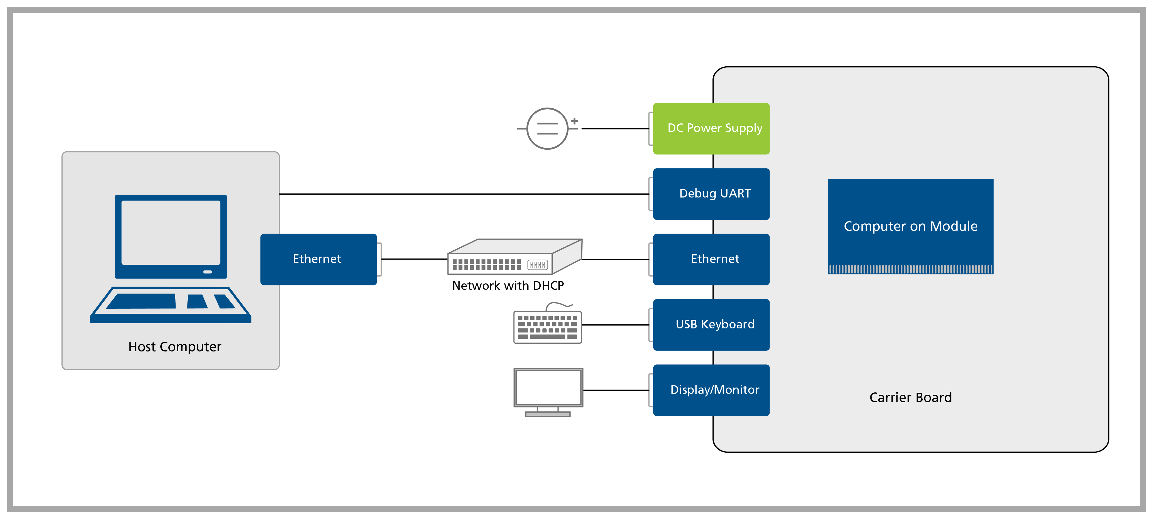
Connect all the cables to your Carrier Board, as demonstrated on the Quickstart Guide for your Carrier Board. Don't forget to connect the display/monitor to the carrier board before power on. HDMI hotplug is not supported.
If don't have a display/monitor available, you can access the user interface remotely over the network using VNC.
Setup cables for your Carrier Board following the QuickStart Guide
Attention: If you are using SoMs based on NVIDIA Tegra SoCs, see the Txx Recovery Mode article for information about how to put the device on Recovery Mode.
Select your computer on module from the tabs below:
Connect the Carrier Board USB OTG port to your Linux or Windows host machine
Apalis Evaluation Board
Connect X49 or X50 (USBO1_CL/USBO1)
Ixora Carrier Board
Connect to X9 on the underside of the Carrier Board. Be sure to remove JP2 in order to be able to use X9 in OTG Client mode. Be sure nothing is plugged into the lower connector of X8.
Using hardware mechanism
There are 2 different methods to enter recovery mode using hardware mechanisms. While alternative 2 is more generic, it is usually a bit clumsier to execute.
Warning: Follow precautions for handling electrostatic sensitive devices (ESD)
Warning: It was reported that on some rare cases with specific combinations of HW, a proper power-cycle (turn the board off and on again) would require that you remove the USB cables due to backfeeding, or even remove the SoM from the carrier board and shorten all its pins. If you cannot enter recovery mode for the second try in a row, consider disconnecting and reconnecting all cables.
Connect the Carrier Board USB OTG port to your Linux or Windows host machine
Apalis Evaluation Board
Connect X49 or X50 (USBO1_CL/USBO1)
Ixora Carrier Board
Connect to X9 on the underside of the Carrier Board. Be sure to remove JP2 in order to be able to use X9 in OTG Client mode. Be sure nothing is plugged into the lower connector of X8.
Using hardware mechanism
There are 3 different methods to enter recovery mode using hardware mechanisms. While alternative 3 is more generic, it is usually a bit clumsier to execute.
Warning: Follow precautions for handling electrostatic sensitive devices (ESD)
Warning: It was reported that on some rare cases with specific combinations of HW, a proper power-cycle (turn the board off and on again) would require that you remove the USB cables due to backfeeding, or even remove the SoM from the carrier board and shorten all its pins. If you cannot enter recovery mode for the second try in a row, consider disconnecting and reconnecting all cables.
Using a command in the bootloader
Connect the serial port UART1 of the carrier board with your host computer.
Apalis Evaluation Board
Depending on JP10/12 connect the serial debug console to the lower X28 using a null modem RS-232 cable or X29 using a regular USB cable.
Ixora Carrier Board
Connect the serial debug console to X22 using a null modem RS-232 cable and a 10 pin IDC to 9 pin D-sub male connector (DTK or Intel standard).
Open a terminal on your host computer (115200 baud, 8 data bits, no parity, one stop, no hardware/software flow control).
Power cycle the board and immediately press [space] on the terminal
If you are using U-Boot you should see the U-Boot banner and the prompt Apalis iMX6 #, in this case, type on the U-Boot command line:
> bmode usb
- If you are using Eboot you should see a menu, in this case, type 'X' to enter the bootloader console, then on the Eboot command line:
> bootfrom USB
> reboot
Connect the Carrier Board USB OTG port to your Linux or Windows host machine
Colibri Evaluation Board
Connect X29 or X30 (USB_CL/USB_OTG)
Iris Carrier Board
Connect X12 micro USB (close to the Ethernet connector)
Aster Carrier Board
Connect a (second) micro USB on X10. Be sure that nothing is plugged at the lower connector of X9.
Warning: Make sure that no SD card is in the SD card slot
There are 3 different methods to enter recovery mode using hardware mechanisms. While alternative 3 is more generic, it is usually a bit clumsier to execute.
Warning: Follow precautions for handling electrostatic sensitive devices (ESD)
Warning: It was reported that on some rare cases with specific combinations of HW, a proper power-cycle (turn the board off and on again) would require that you remove the USB cables due to backfeeding, or even remove the SoM from the carrier board and shorten all its pins. If you cannot enter recovery mode for the second try in a row, consider disconnecting and reconnecting all cables.
Connect the Carrier Board USB OTG port to your Linux or Windows host machine
Colibri Evaluation Board
Connect X29 or X30 (USB_CL/USB_OTG)
Iris Carrier Board
Connect X12 micro USB (close to the Ethernet connector)
Aster Carrier Board
Connect a (second) micro USB on X10. Be sure that nothing is plugged at the lower connector of X9.
Warning: Make sure that no SD card is in the SD card slot
Using hardware mechanism
Warning: Follow precautions for handling electrostatic sensitive devices (ESD)
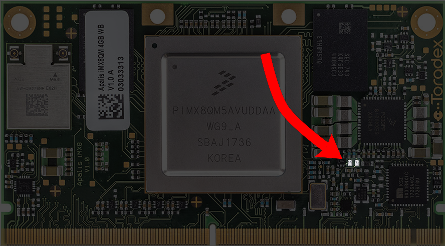
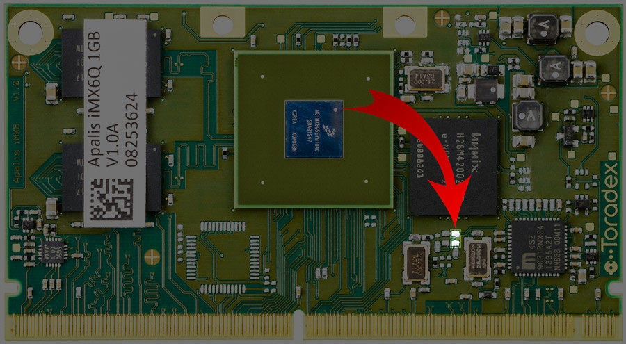
Make sure the board is turned off.
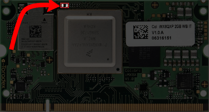
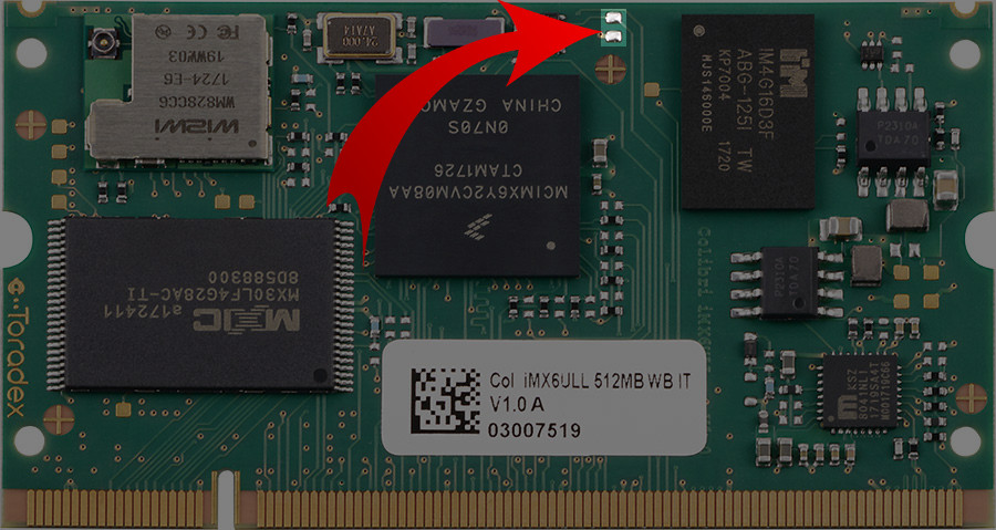
Shorten the pads on the picture.
Note: You can use scissors, tweezers, a paper clip or whatever you have at hand to short circuit the pads. You should not make a permanent short-circuit by e.g. soldering the pads together.
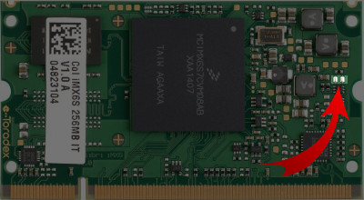
Power on the board and keep the short circuit for more than 6 seconds, only after that, remove the short circuit.
Note: The short circuit should be held only while the board is turning on
Warning: It was reported that on some rare cases with specific combinations of HW, a proper power-cycle (turn the board off and on again) would require that you remove the USB cables due to backfeeding, or even remove the SoM from the carrier board and shorten all its pins. If you cannot enter recovery mode for the second try in a row, consider disconnecting and reconnecting all cables.
Using a command in the bootloader
Connect the serial port UART_A of the carrier board with your host computer.
Depending on JP17/19 (and JP20/JP21 if you use a Carrier Board with V3.2 and later) connect the serial debug console to the bottom X25 using a null modem RS-232 cable or X27 using a regular USB cable.
Connect the serial debug console to X13 using a null modem RS-232 cable and a 10 pin IDC to 9 pin D-sub male connector (DTK or Intel standard).
Open a terminal on your host computer (115200 baud, 8 data bits, no parity, one stop, no hardware/software flow control).
Power cycle the board and immediately press [space] on the terminal
If you are using U-Boot you should see the U-Boot banner and the prompt Colibri iMX6 #, in this case, type on the U-Boot command line:
> bmode usb
- If you are using Eboot you should see a menu, in this case, type 'X' to enter the bootloader console, then on the Eboot command line:
> bootfrom USB
> reboot
Note: Colibri iMX7 Solo/Dual 256/512MB V1.1A and older are not supported by Toradex Easy Installer.
Note: Colibri iMX7 Dual 1GB V1.1A and newer are using an eMMC flash and are supported by Toradex Easy Installer 1.2, 1.3 and 1.6 or newer.
Toradex Easy Installer 1.4 and 1.5 did now work reliably with these modules.
Connect the Carrier Board USB OTG port to your Linux or Windows host machine
Colibri Evaluation Board
Connect X29 or X30 (USB_CL/USB_OTG)
Iris Carrier Board
Connect X12 micro USB (close to the Ethernet connector)
Aster Carrier Board
Connect a (second) micro USB on X10. Be sure that nothing is plugged at the lower connector of X9.
Warning: Make sure that no SD card is in the SD card slot
There are 3 different methods to enter recovery mode using hardware mechanisms. While alternative 3 is more generic, it is usually a bit clumsier to execute.
Warning: Follow precautions for handling electrostatic sensitive devices (ESD)
Warning: It was reported that on some rare cases with specific combinations of HW, a proper power-cycle (turn the board off and on again) would require that you remove the USB cables due to backfeeding, or even remove the SoM from the carrier board and shorten all its pins. If you cannot enter recovery mode for the second try in a row, consider disconnecting and reconnecting all cables.
Note: Colibri iMX6ULL 512MB Wi-Fi/Bluetooth are only supported by Toradex Easy Installer 1.3 and newer.
Connect the Carrier Board USB OTG port to your Linux or Windows host machine
Colibri Evaluation Board
Connect X29 or X30 (USB_CL/USB_OTG)
Iris Carrier Board
Connect X12 micro USB (close to the Ethernet connector)
Aster Carrier Board
Connect a (second) micro USB on X10. Be sure that nothing is plugged at the lower connector of X9.
Warning: Make sure that no SD card is in the SD card slot
Using hardware mechanism
There are 3 different methods to enter recovery mode using hardware mechanisms. While alternative 3 is more generic, it is usually a bit clumsier to execute.
Warning: Follow precautions for handling electrostatic sensitive devices (ESD)
Warning: It was reported that on some rare cases with specific combinations of HW, a proper power-cycle (turn the board off and on again) would require that you remove the USB cables due to backfeeding, or even remove the SoM from the carrier board and shorten all its pins. If you cannot enter recovery mode for the second try in a row, consider disconnecting and reconnecting all cables.
Using a command in the bootloader
Connect the serial port UART_A of the carrier board with your host computer.
Depending on JP17/19 (and JP20/JP21 if you use a Carrier Board with V3.2 and later) connect the serial debug console to the bottom X25 using a null modem RS-232 cable or X27 using a regular USB cable.
Connect the serial debug console to X13 using a null modem RS-232 cable and a 10 pin IDC to 9 pin D-sub male connector (DTK or Intel standard).
Open a terminal on your host computer (115200 baud, 8 data bits, no parity, one stop, no hardware/software flow control).
Power cycle the board and immediately press [space] on the terminal
If you are using U-Boot you should see the U-Boot banner and the prompt Colibri iMX6ULL #, in this case, type on the U-Boot command line:
> bmode usb
The Verdin Family Specification defines an always compatible recovery mode pin on the edge connector of the SoM. The method for entering recovery mode on all Verdin SoMs is the same.
Connect the Carrier Board USB OTG port to your Linux or Windows host machine
Verdin Development Board
Connect X34 USB OTG interface, using a USB Type-C cable.
Dahlia Carrier Board
Connect X3 USB OTG interface, using a USB Type-C cable.
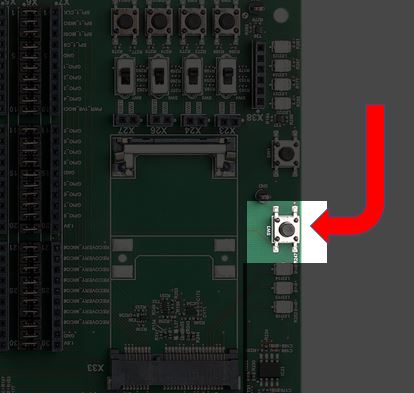
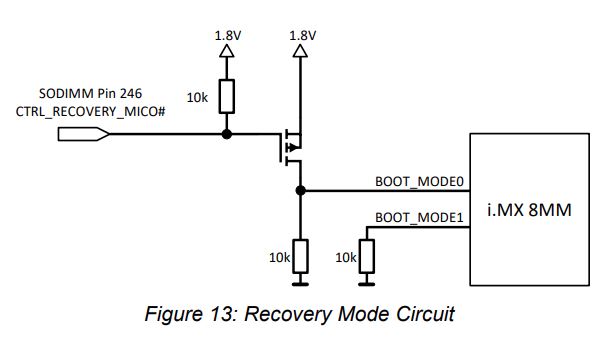
For the Verdin Computer on Modules, there is just one way to enter Recovery Mode, which is by the dedicated recovery pin (SODIMM pin 246), which needs to be pulled down with ≤1kΩ during the initial power on (cold boot) of the module.
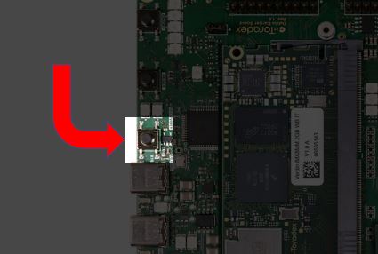
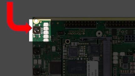
Toradex carrier boards for Verdin come with a dedicated button to manipulate the Recovery Mode mechanism, which is described in detail below for each available model.
Warning: Follow precautions for handling electrostatic sensitive devices (ESD)
Warning: It was reported that on some rare cases with specific combinations of HW, a proper power-cycle (turn the board off and on again) would require that you remove the USB cables due to backfeeding, or even remove the SoM from the carrier board and shorten all its pins. If you cannot enter recovery mode for the second try in a row, consider disconnecting and reconnecting all cables.
To check if your Computer on Module has entered recovery mode correctly, you can compare the output of lsusb on your computer before and after entering recovery mode. A new entry will be present if the procedure has been successful.
Warning: Don't expect any menu on the Display/Monitor at this moment. The Tezi GUI will only show up after the software be loaded on the next step.
Unzip the Toradex Easy Installer package you downloaded at the beginning of the article, change to this directory, and use one of the following scripts on the host machine to load and execute the tool through USB OTG interface:
$ cd <unzipped directory>
$ recovery-windows.bat
Warning: Apalis TK1 does not have a script for Windows. If you want to load Toradex Easy Installed on an Apalis TK1 module, use a Linux PC.
This process might cause multiple device detections on Windows. Avoid using virtualization since the individual re-enumerated USB devices get not routed through to the virtual machine guest automatically.
$ cd <unzipped directory>
$ recovery-linux.sh
Note: During the recovery process, the module connected via USB may re-enumerate several times.
If downloading gets stuck or fails with an error, try starting over from the recovery mode article.
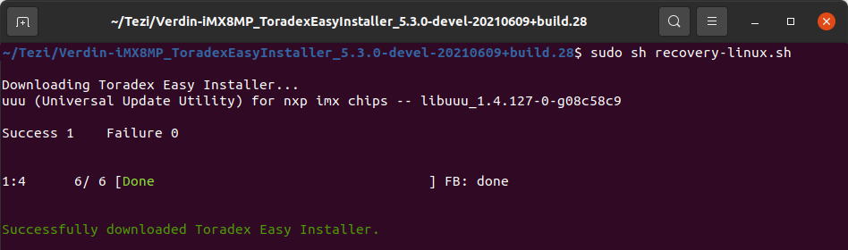
Example of output after successful execution of the recovery script
After loading the Toradex Easy Installer into the module's RAM memory, the Tezi GUI will show up in your Display/Monitor.
Note: This process does not write the Toradex Easy Installer to flash. You will have to redo these steps if you power off your module.
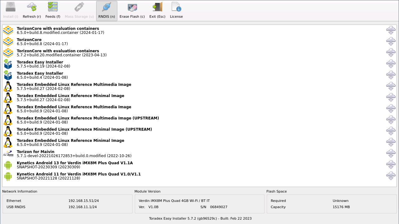
Toradex Easy Installer screen
You are ready to install images using the tool. See the Toradex Easy Installer article for instructions on how to proceed.
")
")
")
")