Warning: This article links to a Product which is going towards EOL (End of Life). Depending on your local Toradex entity, there are very few to none of this product left for sales.
Please also have a look at the main page about EDT Displays.
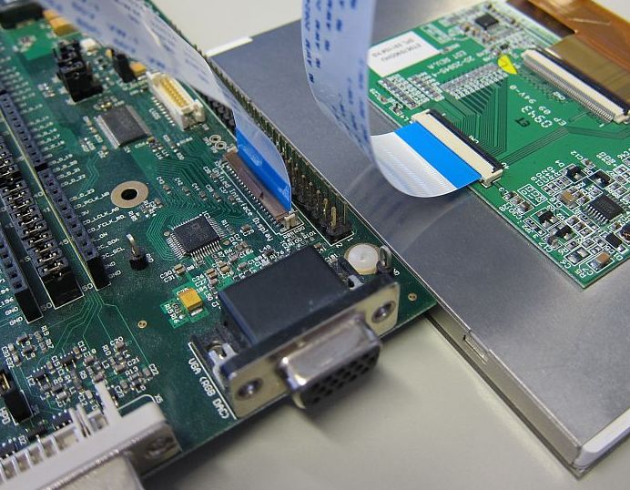
When connecting the EDT displays to a Colibri Evaluation Board or an Iris carrier board, make sure that pin 1 of the display is connected to pin 1 of the board. Due to the nature of the FFC connectors, it is possible to invert the pinout and possibly damage the display and/or carrier board.
Be also careful with the brown levers on the connectors. They are very delicate and can easily break.
Please have a look at the pictures below which show how to connect the cables:

Connecting the EDT 7" display to the Colibri Evaluation Board V3.1
Connecting the EDT 5.7" display to the Colibri Evaluation Board V3.1
For Colibri modules, if you connect it with a standard Colibri Carrier board you may experience that the display does not show to maximum brightness. To get the maximum brightness you need to set the back-light PWM_A signal to output 0.
| Module | Signal Name | SODIMM Pin/MXM pin | GPIO Pin | Display Pin |
|---|---|---|---|---|
| Colibri PXA270 | PWM_A | 59 | 12 | 6(LEDCTRL) |
| Colibri PXA300 | PWM_A | 59 | 20 | 6(LEDCTRL) |
| Colibri PXA310 | PWM_A | 59 | 20 | 6(LEDCTRL) |
| Colibri PXA320 | PWM_A | 59 | 14 | 6(LEDCTRL) |
| Colibri T20 | PWM_A | 59 | B4 Note1 | 6 (LEDCTRL) |
| Colibri T30 | PWM_A | 59 | B4 Note1 | 6 (LEDCTRL) |
| Colibri VF50 | PWM_A | 59 | PTC7 | 6 (LEDCTRL) |
| Colibri VF61 | PWM_A | 59 | PTC7 | 6 (LEDCTRL) |
Note1: SODIMM pin 59 on Colibri T20 and T30 has two CPU signals assigned (multiplexed) L5 and B4. Make sure you set B4 to output 0 and L5 to input.
Whereas, for Apalis T30 on a standard Apalis carrier board use GPIO C.00.
| Module | Signal Name | MXM Pin | GPIO Pin | Display Pin |
|---|---|---|---|---|
| Apalis T30 | BKL1_PWM | 239 | C.00 | 6 (LEDCTRL) |
For a test you can use the GPIOConfig Tool.
To make it permanent you need to set/create the following registry keys for the following modules:
| Module | Registry Location | BL_GPIO | BL_POL | DISP_GPIO | DISP_POL |
|---|---|---|---|---|---|
| Colibri PXA270 | [HKLM\Drivers\Display\Colibri] | 12 | 0 | 81 | 1 |
| Colibri PXA300 | [HKLM\Drivers\Display\Colibri] | 20 | 0 | 39 | 1 |
| Colibri PXA310 | [HKLM\Drivers\Display\Colibri] | 20 | 0 | 39 | 1 |
| Colibri PXA320 | [HKLM\Drivers\Display\Colibri] | 14 | 0 | 49 | 1 |
| Colibri T20 | [HKLM\Software\NVIDIA Corporation\NVDDI\LCD] | 12 | 0 | 156 | 1 |
| Colibri T30 | [HKLM\Software\NVIDIA Corporation\NVDDI\LCD] | 12 | 0 | 170 | 1 |
| Colibri VF50 | [HKLM\Drivers\Display\Colibri] (Image already has in built registry keys.) |
71 | 1 | N/A | N/A |
| Colibri VF61 | [HKLM\Drivers\Display\Colibri] (Image already has in built registry keys.) |
71 | 1 | N/A | N/A |
| Apalis T30 | [HKLM\Software\NVIDIA Corporation\NVDDI\LCD] | 16 | 0 | 170 | 1 |
For example, if you want to set values for Colibri T20 then set/create the registry keys as:
[HKLM\Software\NVIDIA Corporation\NVDDI\LCD]
BL_GPIO  = dword:0x0000000c    ; Backlight GPIO (GPIO B4 on T20/T30)
BL_POL   = dword:0             ; Backlight Polarity
DISP_GPIO= dword:0x0000009c    ; Display Enable GPIO (GPIO T4)
DISP_POL = dword:1             ; Display Enable Polarity
The EDT display are also featuring the touch screen interface on the same FFC.
To calibrate the touchscreen see: Touch Screen => Calibration
To make the calibration permanent, you need to save the registry.
Please find the instructions in the Display Output, Resolution and Timings and Resistive Touch Screen articles.
