Introduction
This article provides information on how to start working on the capacitive multi-touch display, which includes how to set up the hardware (wiring) and install the necessary WinCE drivers for a multi-touch demo.
Capacitive Multi-Touch Display kit
There are two sets of display kits "Capacitive Multi-Touch Display 7" and "Capacitive Multi-Touch Display 10" consisting of a Fusion 7" display touch and Fusion 10" display touch respectively and a capacitive multi-touch adapter. For more information on the topic, see Capacitive Multi-Touch Display.
Getting Started
Wiring a capacitive multi-touch adapter board with multi-touch display:
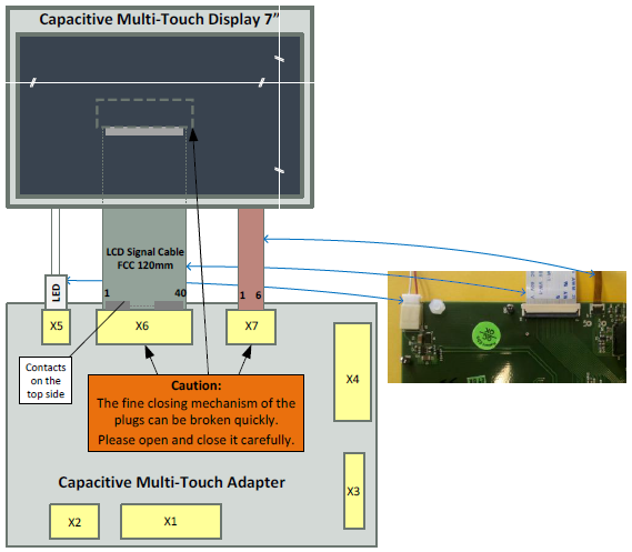
- Multi-Touch Display 7”
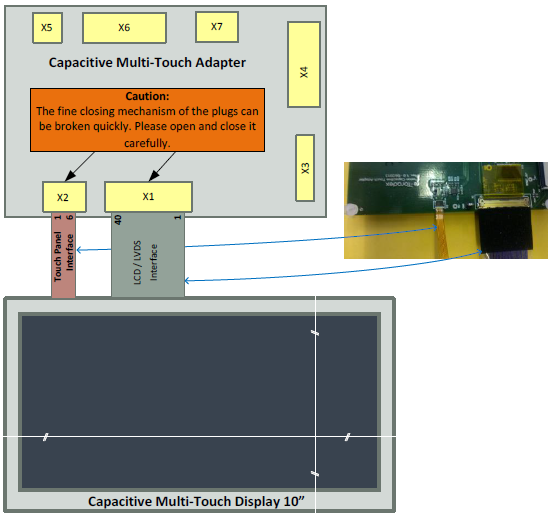
- Multi-Touch Display 10”
The images shown below are helpful in providing a general overview, but please note that the parts depicted in these images can change over time (color, etc.). In case of ambiguity, please consider the schematics and assembly drawing from Capacitive Multi-Touch Display page. Connect the chosen display and carrier board to the multi-touch adapter.
Once the wiring is completed, you will need to install the driver. Click here to directly go to multi-touch driver.
Note: X3 and X6 are the same type of connectors for FCC cable. Do not connect the flat cable from the carrier board to the X6 connector! If you do so, it will result in damaging either the adapter or the carrier board!
Capacitive Multi-Touch Display Wiring with Capacitive Touch Adapter board
Wiring of both the displays - Capacitive Multi-Touch Display 10" and Display 7" with capacitive multi-touch adapter board is different depending upon the type of display.
Using 10" Display
This topic describes how to connect the Capacitive Multi-Touch Display 10” to the capacitive touch adapter.
The LVDS LCD interface of the Display 10" can be connected to the X1 connector using the LVDS cable. The small, flat cable for the touch controller can be connected directly to the X2 connector (see the schematic diagram above).
The FCC cable to the carrier board is connected to the X3 connector of the Capacitive Touch Adapter Board with Blue ribbon side up. Match the other end of the FCC cable's 1-40 pins properly to the respective carrier boards unified Interface display connector.
Using 7" Display
This topic describes how to connect the Capacitive Multi-Touch Display 7” to the capacitive touch adapter.
The LCD interface of the Display 7” can be connected to the X6 connector using the FCC cable.
Note: The blue ribbon side of the FCC cable should be UP on the Display and DOWN on the Capacitive Touch Adapter Board.
The small, flat cable for the touch controller can be connected directly to the X7 connector (see the schematic diagram above).
The FCC cable to the carrier board is connected to the X3 connector of the Capacitive Touch Adapter Board with Blue ribbon side up. Match the other end of the FCC cable's 1-40 pins properly to the respective carrier boards unified Interface display connector.
Carrier Board Connections
This topic provides pin connection details of all the carrier boards with capacitive multi-touch adapter boards. Refer to the table below for various pin connections of capacitive multi-touch adapter board with carrier boards:
| Adapter | Colibri Evaluation Board | Iris Carrier Board | Viola Carrier Board | Apalis Evaluation Board | Ixora Carrier Board |
|---|---|---|---|---|---|
| X3 | X34 | X3 (back side) | X7 (back side) | X31 | X15 |
| X4/1 (GND) | Not connected | Not connected | Not connected | Not connected | Not connected |
| X4/2 (3V3_IN) | X9/43 (3.3V) | X16/33 (3.3V) | X9/4 (3.3V) | X2/16 (3.3V) | X27/29 (3.3V) |
| X4/3 (5V_IN) | JP24/3 (5V) | X16/12 (5V) | X9/1 (5V) | JP14/3 (5V) | X27/12 (5V) |
| X4/4 (GND) | X9/49(GND) | X16/3 (GND) | X9/7 (GND) | X2/11 (GND) | X27/32(GND) |
| X4/5 (DISP_ON) | Not connected | Not connected | Not connected | Not connected | Not connected |
| X4/6 (TOUCH_I2C_SCL_3.3V) | X9/48(SODIMM_196) | X16/6 (SODIMM_196) | X9/5 (SODIMM_196) | X8/39(I2C1_SCL/MXM3_211) | X27/6(I2C1_SCL) |
| X4/7 (TOUCH_I2C_SDA_3.3V) | X9/47(SODIMM_194) | X16/5 (SODIMM_194) | X9/6 (SODIMM_194) | X8/40(I2C1_SDA/MXM3_209) | X27/5(I2C1_SDA) |
| X4/8 (TOUCH_INT_3.3V) | X10/38 (SODIMM_107) | X16/38 (SODIMM_28) | X9/42 (SODIMM_28) | X2/6 (GPIO5/MXM3_11) | X27/17 (GPIO5) |
| X4/9 (TOUCH_RESET_3.3V) | X10/39 (SODIMM_106) | X16/39 (SODIMM_30) | X9/43 (SODIMM_30) | X2/5 (GPIO6/MXM3_13) | X27/18 (GPIO6) |
| X4/10 (GND) | X10/50 (GND) | X16/36 (GND) | X9/40 (GND) | not connected | (GND) |
WinCE
Multi-Touch Driver Installation
In the past, Toradex created custom capacitive touch drivers (single- or multi-touch) for every specific device and certain OS versions. Because there were no defined standards to connect capacitive touch devices, this resulted in a variety of touch drivers.
The multi-touch solution from Toradex gives the customer the opportunity to write and maintain their own touch drivers with little effort.
The capacitive multi-touch solution is a concept to generate a customized multi-touch driver for a particular touch controller very easily. For more information, see Capacitive Multi-Touch Solution.
The setup program for the multi-touch solution will request to list the used display type and carrier board. It will then install all executable files and make the necessary modifications in the registry.
| Modules (Colibri / Apalis) | PXA270 | PXA300 | PXA320 | T20 | VF50 | VF61 | T30 | iMX6 |
|---|---|---|---|---|---|---|---|---|
| Windows Embedded CE 5.0 (CE5) | -- | -- | -- | -- | -- | -- | -- | -- |
| Windows Embedded CE 6.0 (CE6) [1] | ok | ok | ok | ok | ok | ok | -- | -- |
| Windows Embedded Compact 7 (CE7) [2] | -- | -- | -- | ok | ok | ok | ok | ok |
| Windows Embedded Compact 2013 (CE8) [2] | -- | -- | -- | -- | ok | ok | ok | ok |
- Setup for Capacitive Multi-Touch Solution for WCE6/WEC7 modules
- Setup for Capacitive Multi-Touch Solution for WEC2013 modules
Download touch demo application for the respective OS below:
Note :
[1] Supports single-touch and gestures.
[2] Supports multi-touch, single-touch, and gestures.
Registry Settings
Registry Settings: After installing the multi-touch driver, current settings in the registry can be viewed, exported, and edited with the help of registry editor on the module:
Start->Programs->ColibriTool->RegEdit Display Settings: Click here.
Display Rotation: Click here.
Multi-Touch Hardware Adaption: The current hardware adaption (connection to the carrier board) is stored at:
[HKEY_LOCAL_MACHINE\Software\Toradex\MultiTchHwAdapt] Information about the registry settings of the hardware adaption can be found on Capacitive Multi-Touch Solution.Unified Multi-Touch Driver: The settings are stored at:
[HKEY_LOCAL_MACHINE\Drivers\Touch] [HKEY_LOCAL_MACHINE\HARDWARE\DEVICEMAP\TOUCH] [HKEY_LOCAL_MACHINE\SYSTEM\GWE\TouchProxy] The Unified Multi-Touch driver is based on the example of a multi-touch driver from Microsoft. Therefore, information about the registry settings of the Unified multi-touch driver can be found on Capacitive Multi-Touch Solution.Touch Calibration: The Unified multi-touch driver uses the calibration data generated by the standard calibration tool:
Start->Settings->ControlPanel->Stylus The calibration data is stored at:
[HKEY_LOCAL_MACHINE\HARDWARE\DEVICEMAP\TOUCH] Information about the touch calibration can be found at the MSDN.NOTE: Do not forget to save the registry.
Bringing up the Touch Panel
After the hardware setup, driver installation, and registry settings are completed, the following steps and tools will help to bring up the device:
- The display should show the Windows CE desktop without any border, flicker, etc. Click here for more details including, checking the documents for general functionality, multi-touch hardware adaption fusion.
- In rare cases, if some part of the text on the Touch Display 10” is not readable, change the pixel clock polarity to zero. Click here to know more about it.
- In rare cases, if you experience I2C failures of Vybrid Modules with connected touch, reducing pull-up resistor value may be of valuable help. 1.8K pull-up can give the better result.
Recommendations to evaluate touch on different CoMs:
- For PXA Modules: Please press and hold the touch device till booting to RESET the inactive state. For more information, please refer this article. If the Touch reset pin is connected with GPIO 26, set the GPIO direction as output and level as 0 by using GPIO config block settings.
- For Tegra Modules: If you are adapting another touch device, please use library v2.1 or newer Windows CE Libraries and Code Samples.
- For Vybrid Modules: Use WinCE image v1.2 or newer images.
- For iMX6 Modules: When detecting the touch events, the mouse cursor will be visible in the Colibri and Apalis modules for every WinCE version. Currently, the display rotation is not working on Apalis iMX6 WinCE. The issue will be resolved in the 1.0 beta 5 release.
Controlling the wiring of the Reset and Interrupt lines:
- It can be done with GPIO Config Tool. With this tool. the chosen SODIMM or MXM3 pin for the Interrupt can be monitored and the Reset pin can be set to high and low.
To Control the wiring of the I2C Bus (SDA, SCL signals):
- Run the I2C demo tool to scan the I2C addresses which is part of the package in the Toradex CE libraries and code samples. The tool shows the I2C addresses of all devices on the I2C bus. One of these addresses should be the address of the touch controller. (Please note that the shown addresses are the addresses of the devices on the I2C bus and not the addresses set in the registry.)
- Please check if the Reset pin is in its inactive state (level is 0) so that the touch controller of the display can run.
- Install the Unified multi-touch driver and control whether the driver is loaded at the startup of the module.
- Install the Hardware Adaption Fusion application and control whether the program is loaded at startup of the module.
- Check if the touch panel is working.
Reinstall the Multi-Touch Driver
It is possible to reinstall the multi-touch driver with other options. Because some files are already installed and in use, one or more windows like shown below may pop up:
Choose "No" to continue with the installation.
If you need to switch between Tegra T20/T30 module and VF50/VF61 module options, then the directory "\FlashDisk\Autotun\" must be cleaned (rename and reset the module) before the directory or its containing files can be deleted.
Embedded Linux
Our Embedded Linux BSP supports capacitive multi-touch screens in single-touch mode. However, while the lower stack (driver and X-Server) supports multi-touch, the desktop environment doesn't make use of it. Also, there is no gesture engine inside the driver or X-Server itself.
Read more about Capacitive Multi-Touch Display (Linux)


