Early test samples of the Colibri VF50 and Colibri VF61 were delivered without SoC Fusing. These modules require a different recovery method.
This article describes how to recover a Colibri VF50/VF61 which does not boot into the bootloader anymore.
Use the following table to determine whether you are working with a fused or non-fused module.
| Module | Version | Fusing Status |
|---|---|---|
| VF50 | V1.0x | non-fused |
| VF50 | V1.1A and higher | fused |
| VF50IT | V1.1A and higher | fused |
| VF61 | V1.0x | non-fused |
| VF61IT | V1.0x | non-fused |
| VF61IT | V1.1A | non-fused |
| VF61IT | V1.1B and higher | fused |
Download the latest recovery image file.
Use the dd command to write the file contents directly to the SD card.
Download the Win32 Disk Imager tool.
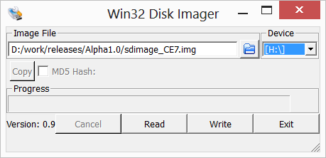
Launch the tool and browse to the .img file you extracted from the download package (in the new releases is named wince.img).
Select your SD card drive letter in the [Device] combo box and select [Write].
Warning: Be careful! The selected drive will be erased!
The tool does not limit your selection to SD card, it reports all removable devices connected to your PC!
See the picture below for a sample.

Insert the SD card in the SD/MMC socket of the Evaluation Board
Install 6 resistors on the Evaluation Board X8 connector:
| SODIMM Pin | Evalboard V3.1 X9 pin |
Connect 1k To |
|---|---|---|
| 80 | 21 | 3.3V |
| 46 | 23 | GND |
| 50 | 27 | 3.3V |
| 57 | 33 | GND |
| 61 | 34 | 3.3V |
| 68 | 44 | 3.3V |

Setup a serial port connection by one of the following options:
Connect a USB cable to the X27 (RS232) connector. Verify that the JP17 and JP19 are in the USB position.
Connect a Null-Modem cable to the X25 (UART-A) connector. Verify that the JP17 and JP19 are in the non-USB position.
Open your favorite terminal application and configure the serial port as 115200bps,8 data bits, 1 stop bit, no parity (8N1).
Then you can power-on the board and see the boot messages on your serial terminal.
Toradex Bootloader 1.0 for Colibri Built Aug 13 2014
Booting from fuses.
Processor ID 410fc051.
Colibri VF50 module version 1.0A

Press [SPACE] to enter Bootloader Menu

Initiating image download in 1 seconds.
If you can't see any serial output, check the resistors and check that the module is correctly plugged in the socket.
Press space in the first 2 seconds after power-up to enter the boot menu.
BootLoader Configuration:

X) Enter CommandPrompt Mode
D) Download image to RAM now
F) Download image to FLASH now
L) Launch existing flash resident image now
Enter your selection:
Press 'x' to enter the CommandPrompt mode.
First we need to make the device bootable by writing the Boot Control Block on the NAND flash.
We must erase the first block of flash:
>eraseflash 0 128kb
Are you sure you want to erase flash(0x0-0x1FFFF)?y
Erasing 1 flash blocks from 0.
. done.
Then we have to write the BCB:
>writebcb
Writing FCB...
Checking FCB...
System is ready to boot.
Use flashloader to write a bootloader before you reset the device.
The boot block contains also some device-specific ids. We need to restore them.
Each module has a sticker with this information in the following format:
Col type
V version
serial
Type the restorefactoryinfo command using the information on your module's sticker:
>restorefactoryinfo *modulecode* *serial* *ver*
The modulecode parameter has four valid values: VF50128, VF50128IT, VF61256, and VF61256IT. Example:
>restorefactoryinfo VF61256 04790168 1.0B
Now e-boot can be written to the NAND flash.
>flashloader
Bootloader image size: 262144 bytes.

Loading done.
Flashing bootloader.
Writing 128 sector(s) of bootloader code from sector 64.

Erasing block 1
................................................................
Erasing block 2
................................................................
Erasing block 3
.
Flashing completed.
Power off the system
Resetting the system is not sufficient, the strapping options are only read after a power-up.
Remove the strapping resistors
Remove the bootable SD card
Your module is now ready to boot from the internal flash.
But only the bootloader has been programmed. The next step is to program the operating system. The procedure is the same as for fused modules. Please refer to the article for fused modules: