This article shows how to configure Linux to use the Fusion 7" and 10" capacitive multi-touch displays. The multi-touch controller is connected using the I2C bus. Our Linux BSPs come with the fusion_F0710A (CONFIG_TOUCHSCREEN_FUSION_F0710A) driver which supports the multi-touch controller. The driver needs configuration data containing the information on how the controller is connected to the device (I2C bus and GPIO information).
The Kernel for Tegra based modules provides the platform data by default. Hence, enabling the driver is simply a matter of loading the kernel module.
On our device tree enabled Kernel (Vybrid and i.MX6 based modules), this platform data is by default disabled due to conflicting pin configurations. Hence enabling the driver on those kernels requires rebuilding the device tree.
Setup Hardware
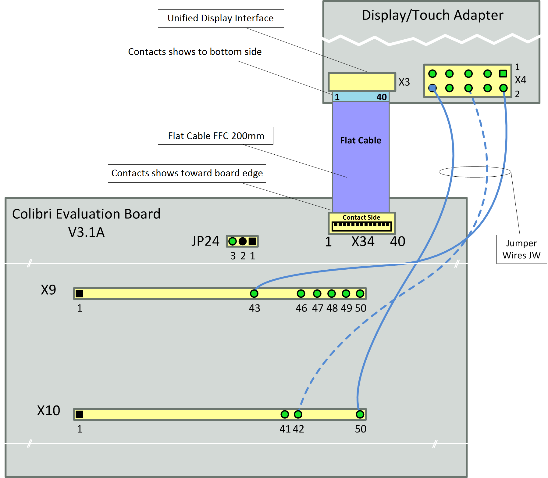
Refer to the general product page Capacitive Multi Touch Display concerning how to hook up your carrier board to the adapter board connected to a particular multi-touch display. However, for historical reasons, the connection to the board differs slightly on Linux compared to WinCE (on Linux, both the Colibri Evaluation Board and the Iris use the same pins).
Connection to the Viola Carrier Board
Wiring
| Adapter | Viola Carrier Board | Cable/Jumper Wire |
|---|---|---|
| X3 | X7 (on the back side) | FCC 200mm |
| X4/1 (GND) | not connected | |
| X4/2 (3V3_IN) | X9/4 (3.3V) | JW female to female |
| X4/3 (5V_IN) | X9/1 (5V) | JW female to female |
| X4/4 (GND) | X9/7 (GND) | JW female to female |
| X4/5 (DISP_ON) | not connected 1) | |
| X4/6 (TOUCH_I2C_SCL_3.3V) | X9/5 (SODIMM_196) | JW female to female |
| X4/7 (TOUCH_I2C_SDA_3.3V) | X9/6 (SODIMM_194) | JW female to female |
| X4/8 (TOUCH_INT_3.3V) | X9/42 2) (SODIMM_28) | JW female to female |
| X4/9 (TOUCH_RESET_3.3V) | X9/43 2) (SODIMM_30) | JW female to female |
| X4/10 (GND) | X9/36 (GND) | JW female to female |
1) display is on by default
2) Viola Carrier Board V1.0: X4/8 to X9/44, X4/9 to X9/41
Connection to the Iris Carrier Board
Wiring
| Adapter | Iris Carrier Board | Cable/Jumper Wire |
|---|---|---|
| X3 | X3 (on the back side) | FCC 200mm |
| X4/1 (GND) | not connected | |
| X4/2 (3V3_IN) | X16/33 (3.3V) | JW female to female |
| X4/3 (5V_IN) | X16/12 (5V) | JW female to female |
| X4/4 (GND) | X16/3 (GND) | JW female to female |
| X4/5 (DISP_ON) | not connected 1) | |
| X4/6 (TOUCH_I2C_SCL_3.3V) | X16/6 (SODIMM_196) | JW female to female |
| X4/7 (TOUCH_I2C_SDA_3.3V) | X16/5 (SODIMM_194) | JW female to female |
| X4/8 (TOUCH_INT_3.3V) | X16/38 (SODIMM_28) | JW female to female |
| X4/9 (TOUCH_RESET_3.3V) | X16/39 (SODIMM_30) | JW female to female |
| X4/10 (GND) | X16/36 (GND) | JW female to female |
1) display is on by default
Connection to the Colibri Evaluation Board
Wiring
| Adapter | Colibri Evaluation Board | Cable/Jumper Wire |
|---|---|---|
| X3 | X34 | FCC 200mm |
| X4/1 (GND) | not connected | |
| X4/2 (3V3_IN) | X9/43 (3.3V) | JW male to female |
| X4/3 (5V_IN) | JP24/3 (5V) | JW female to female |
| X4/4 (GND) | X9/49(GND) | JW male to female |
| X4/5 (DISP_ON) | not connected 1) | |
| X4/6 (TOUCH_I2C_SCL_3.3V) | X9/48(SODIMM_196) | JW male to female |
| X4/7 (TOUCH_I2C_SDA_3.3V) | X9/47(SODIMM_194) | JW male to female |
| X4/8 (TOUCH_INT_3.3V) | X10/27 (SODIMM_28) | 2x JW male to female |
| X4/9 (TOUCH_RESET_3.3V) | X10/28 (SODIMM_30) | 2x JW male to female |
| X4/10 (GND) | X10/50 (GND) | 2x JW male to female |
1) display is on by default
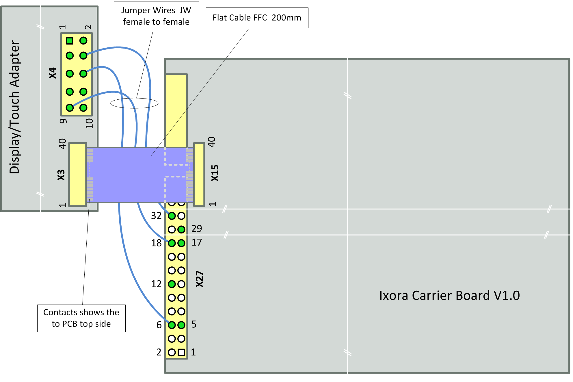
Connection to the Ixora Carrier Board
Wiring
| Adapter | Ixora Carrier Board | Cable/Jumper Wire |
|---|---|---|
| X3 | X15 | FCC 200mm |
| X4/1 (GND) | not connected | |
| X4/2 (3V3_IN) | X27/29 (3.3V) | JW female to female |
| X4/3 (5V_IN) | X27/12 (5V) | JW female to female |
| X4/4 (GND) | X27/32(GND) | JW female to female |
| X4/5 (DISP_ON) | not connected 1) | |
| X4/6 (TOUCH_I2C_SCL_3.3V) | X27/6(I2C1_SCL) | JW female to female |
| X4/7 (TOUCH_I2C_SDA_3.3V) | X27/5(I2C1_SDA) | JW female to female |
| X4/8 (TOUCH_INT_3.3V) | X27/17 (GPIO5) | JW female to female |
| X4/9 (TOUCH_RESET_3.3V) | X27/18 (GPIO6) | JW female to female |
| X4/10 (GND) | not connected |
1) display is on by default
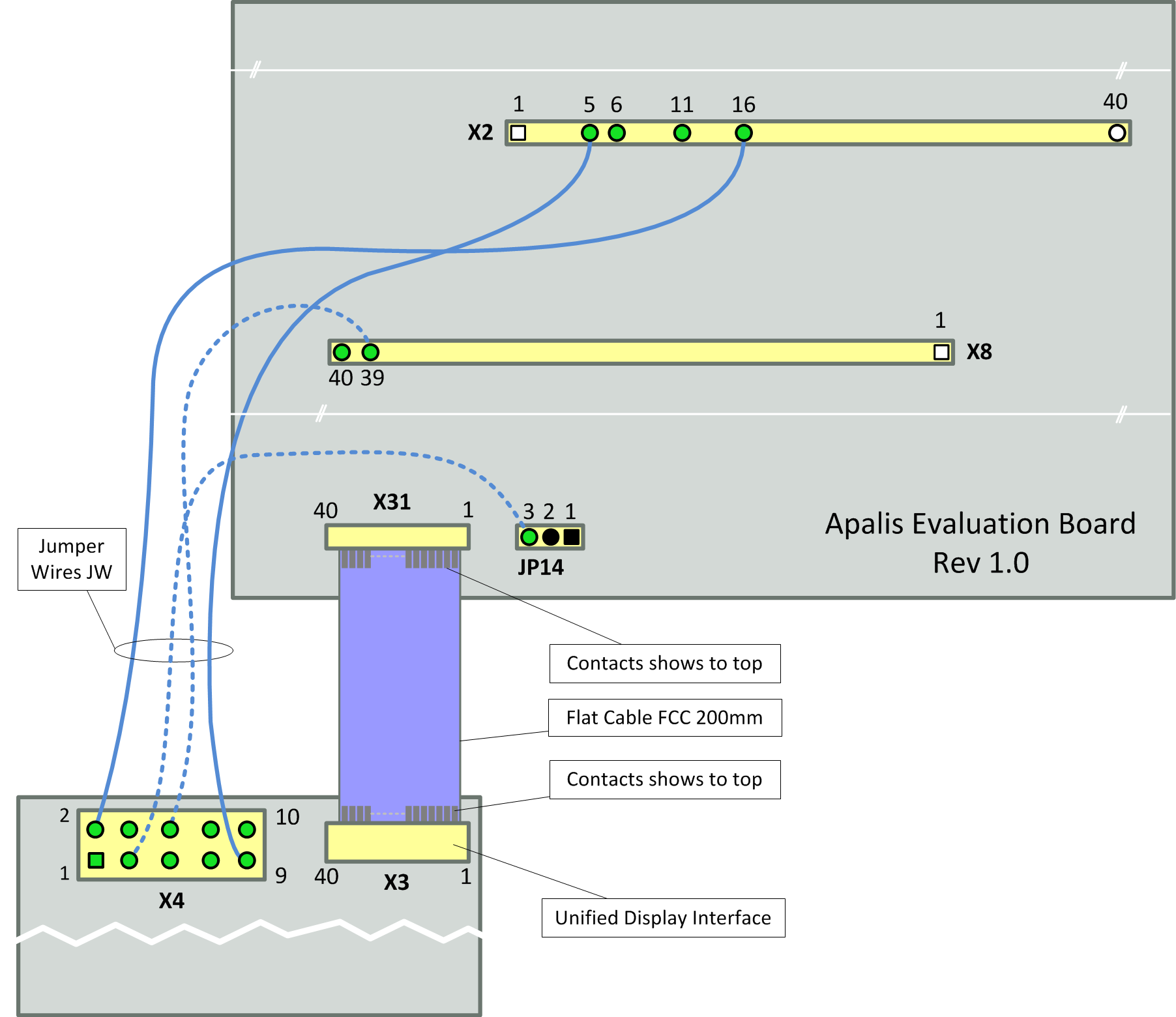
Connection to the Apalis Evaluation Board
Wiring
| Adapter | Apalis Evaluation Board | Cable/Jumper Wire |
|---|---|---|
| X3 | X31 | FCC 200mm |
| X4/1 (GND) | not connected | |
| X4/2 (3V3_IN) | X2/16 (3.3V) | JW male to female |
| X4/3 (5V_IN) | JP14/3 (5V) | JW female to female |
| X4/4 (GND) | X2/11 (GND) | JW male to female |
| X4/5 (DISP_ON) | not connected 1) | |
| X4/6 (TOUCH_I2C_SCL_3.3V) | X8/39(I2C1_SCL/MXM3_211) | JW male to female |
| X4/7 (TOUCH_I2C_SDA_3.3V) | X8/40(I2C1_SDA/MXM3_209) | JW male to female |
| X4/8 (TOUCH_INT_3.3V) | X2/6 (GPIO5/MXM3_11) | JW male to female |
| X4/9 (TOUCH_RESET_3.3V) | X2/5 (GPIO6/MXM3_13) | JW male to female |
| X4/10 (GND) | not connected |
1) display is on by default
Software Setup
Display Configuration
To configure the display resolution, different methods are available. The Linux kernel arguments method (e.g. by using the U-Boot serial console to alter the vidargs environment variable) works on all our modules.
Refer to the article "Display Output, Resolution and Timings (Linux)" for more information.
Some displays are able to work with various timings but others only work if correct timings are configured.
Altering the Device Tree
This step is only required for device tree enabled kernels (Vybrid, i.MX 6, i.MX7 and iMX6ULL based modules). For detailed information how to alter and rebuild the device tree, refer to the Device Tree Customization article.
On Colibri modules the multi-touch controller uses the PWM_B/PWM_C pins as pen down and reset interrupt, so the PWM functionality on these pins has to be disabled and the relevant GPIO functionality enabled and assigned to the touch driver.
Colibri VF
On Vybrid, the pins for PWM_B/PWM_C need to be removed from the pinctrl list by overwriting the pinctrl-0 property:
diff --git a/arch/arm/boot/dts/vf-colibri-eval-v3.dtsi b/arch/arm/boot/dts/vf-colibri-eval-v3.dtsi
index e834275..082d5bf 100644
--- a/arch/arm/boot/dts/vf-colibri-eval-v3.dtsi
+++ b/arch/arm/boot/dts/vf-colibri-eval-v3.dtsi
@@ -230,7 +230,7 @@
                gpios = <&gpio0 30 GPIO_ACTIVE_HIGH /* SO-DIMM 28, Pen down interrupt */
                         &gpio0 23 GPIO_ACTIVE_LOW /* SO-DIMM 30, Reset interrupt */
                        >;
-               status = "disabled";
+               status = "okay";
        };

        /* M41T0M6 real time clock on carrier board */
@@ -242,10 +242,12 @@

 &pwm0 {
        status = "okay";
+       pinctrl-0 = <&pinctrl_pwm0_a>;
 };

 &pwm1 {
        status = "okay";
+       pinctrl-0 = <&pinctrl_pwm1_d>;
 };

 &tcon0 {
(on 3.18 based kernel, the PWM pinctrl nodes look slightly different. In this case, vf-colibri.dtsi need to be altered to remove the PWM_B/PWM_C pins)
By default, the PWM frequency is 200 Hz.
The Fusion 7" requires a frequency of 10 kHz to work reliably. The PWM pulse width can be overwritten in the backlight node of the carrier board level device tree (the period is specified in nano seconds):
--- a/arch/arm/boot/dts/vf-colibri-eval-v3.dtsi
+++ b/arch/arm/boot/dts/vf-colibri-eval-v3.dtsi
@@ -79,6 +79,7 @@
 &bl {
        brightness-levels = <0 4 8 16 32 64 128 255>;
        default-brightness-level = <6>;
+       pwms = <&pwm0 0 100000 0>;
        status  = "okay";
 };
The U-Boot version deployed with V2.5 Beta 1 and later executes the variable 'fdt_fixup' after the device tree has been loaded. This allows boot-time adjustments to be made to the device tree. Using this mechanism, the same as above may be achieved (temporarily) by defining the new 'fdt_fixup' variable:
setenv fdt_fixup 'fdt addr ${fdt_addr_r} && fdt resize && fdt set /backlight pwms <0x00000034 0x00000000 0x000186A0 0x00000000>'
saveenv
Note that the enumeration of &pwm0 (the 0x34 above) may have been changed in the device tree you are using.
The following shows how one display the current setting from U-Boot. In this example the enumaration did in fact change to 0x3a, the periode is still set to the default 0x004c4b40 = 5000000 ns.
Colibri VFxx # ubi part ubi; ubi read ${fdt_addr_r} dtb;fdt addr ${fdt_addr_r}
...
Colibri VFxx # fdt print /backlight pwms
pwms = <0x0000003a 0x00000000 0x004c4b40 0x00000000>
Colibri iMX6
The PCAP preprocessor macro needs to be defined at the top of the device tree.
diff --git a/arch/arm/boot/dts/imx6dl-colibri-eval-v3.dts b/arch/arm/boot/dts/imx6dl-colibri-eval-v3.dts
index e2b8e9e..c70d4f4 100644
--- a/arch/arm/boot/dts/imx6dl-colibri-eval-v3.dts
+++ b/arch/arm/boot/dts/imx6dl-colibri-eval-v3.dts
@@ -19,7 +19,7 @@

 /* Add the following define if you connect a Fusion display with a capacitive
    touch controller */
-/* #define PCAP */
+#define PCAP

 / {
        model = "Toradex Colibri iMX6DL/S on Colibri Evaluation Board V3";
The Fusion 7" requires a frequency of 10 kHz to work reliably. This can be specified in the backlight node of the carrier board level device tree:
diff --git a/arch/arm/boot/dts/imx6dl-colibri-eval-v3.dts b/arch/arm/boot/dts/imx6dl-colibri-eval-v3.dts
index b33dbdd..defcf08 100644
--- a/arch/arm/boot/dts/imx6dl-colibri-eval-v3.dts
+++ b/arch/arm/boot/dts/imx6dl-colibri-eval-v3.dts
@@ -82,8 +82,8 @@
 };

 &backlight {
-#if 0 /* PWM polarity: if 1 is brightest */
-#if 0 /* Fusion 7 needs 10kHz PWM frequency */
+#if 1 /* PWM polarity: if 1 is brightest */
+#if 1 /* Fusion 7 needs 10kHz PWM frequency */
        pwms = <&pwm3 0 100000>;
 #endif
        brightness-levels = <0 4 8 16 32 64 128 255>;
Apalis iMX6
There is no need to alter the device tree on Apalis i.MX6 for the Fusion 10” display. The relevant nodes are enabled by default.
The Fusion 7" display requires a frequency of 10 kHz to work reliably. This can be specified in the backlight node of the carrier board level device tree:
diff --git a/arch/arm/boot/dts/imx6qdl-apalis-eval.dtsi b/arch/arm/boot/dts/imx6qdl-apalis-eval.dtsi
index a6e1aac..fc064af 100644
--- a/arch/arm/boot/dts/imx6qdl-apalis-eval.dtsi
+++ b/arch/arm/boot/dts/imx6qdl-apalis-eval.dtsi
@@ -111,8 +111,8 @@
 };

 &backlight {
-#if 0 /* PWM polarity: if 1 is brightest */
-#if 0 /* Fusion 7 needs 10kHz PWM frequency */
+#if 1 /* PWM polarity: if 1 is brightest */
+#if 1 /* Fusion 7 needs 10kHz PWM frequency */
        pwms = <&pwm4 0 100000>;
 #endif
        brightness-levels = <0 4 8 16 32 64 128 255>;
Colibri iMX7
On i.MX7 based devices the two PWM instances need to be disabled (which also frees the pins required by the Fusion I2C node) and the Fusion I2C multi-touch controller need to be enabled.
--- a/arch/arm/boot/dts/imx7-colibri-eval-v3.dtsi
+++ b/arch/arm/boot/dts/imx7-colibri-eval-v3.dtsi
@@ -80,7 +81,7 @@
                        /* SODIMM 30, Reset interrupt */
                         &gpio1 10 GPIO_ACTIVE_LOW
                        >;
-               status = "disabled";
+               status = "okay";
        };

        /* M41T0M6 real time clock on carrier board */
@@ -202,11 +218,11 @@
 };

 &pwm2 {
-       status = "okay";
+       status = "disabled";
 };

 &pwm3 {
-       status = "okay";
+       status = "disabled";
 };

 &pwm4 {
The Fusion 7" requires a frequency of 10 kHz to work reliably. The frequency can be overwritten in the backlight node of the carrier board level device tree:
--- a/arch/arm/boot/dts/imx7-colibri-eval-v3.dtsi
+++ b/arch/arm/boot/dts/imx7-colibri-eval-v3.dtsi
@@ -27,6 +27,7 @@
 &bl {
        brightness-levels = <0 4 8 16 32 64 128 255>;
        default-brightness-level = <6>;
+       pwms = <&pwm1 0 100000 0>;
        status = "okay";
 };
Colibri iMX6ULL
Also on i.MX6 ULL based devices, the two PWM instances need to be disabled (which also frees the pins required by the Fusion I2C node) and the Fusion I2C multi-touch controller needs to be enabled.
--- a/arch/arm/boot/dts/imx6ull-colibri-eval-v3.dtsi
+++ b/arch/arm/boot/dts/imx6ull-colibri-eval-v3.dtsi
@@ -137,7 +138,7 @@
                        /* SODIMM 30, Reset interrupt */
                         &gpio2 5 GPIO_ACTIVE_LOW
                        >;
-               status = "disabled";
+               status = "okay";
        };

        /* M41T0M6 real time clock on carrier board */
@@ -283,12 +284,12 @@

 /* PWM <B> */
 &pwm5 {
-       status = "okay";
+       status = "disabled";
 };

 /* PWM <C> */
 &pwm6 {
-       status = "okay";
+       status = "disabled";
 };
Furthermore, for the touchscreen driver to load correctly, make sure GPIO2_IO5 is available for the I2C interface by making the following change:
--- a/arch/arm/boot/dts/imx6ull-colibri-eval-v3.dtsi
+++ b/arch/arm/boot/dts/imx6ull-colibri-eval-v3.dtsi
 /* PWM <D> */
@@ -349,7 +350,7 @@
                pinctrl_gpiotouch: touchgpios {
                        fsl,pins = <
                                MX6UL_PAD_NAND_DQS__GPIO4_IO16          0x74
-                               MX6UL_PAD_ENET1_TX_EN__GPIO2_IO05       0x14
+                               MX6UL_PAD_ENET1_TX_EN__GPIO2_IO05       0x74
                        >;
                };
        };
The Fusion 7" requires a frequency of 10 kHz to work reliably. The frequency can be overwritten in the backlight node of the carrier board level device tree:
--- a/arch/arm/boot/dts/imx6ull-colibri-eval-v3.dtsi
+++ b/arch/arm/boot/dts/imx6ull-colibri-eval-v3.dtsi
@@ -75,7 +75,8 @@
 &bl {
        brightness-levels = <0 4 8 16 32 64 128 255>;
        default-brightness-level = <6>;
+       pwms = <&pwm4 0 100000 1>;
        status = "okay";
 };
Altering the Platform Data
The Fusion 7" display requires a frequency of 10 kHz to work reliably. For Apalis/Colibri T20/T30 this can be specified in the Linux kernel's platform data. E.g. for Apalis T30:
diff --git a/arch/arm/mach-tegra/board-apalis_t30-panel.c b/arch/arm/mach-tegra/board-apalis_t30-panel.c
index 1be339d..9f8a383 100644
--- a/arch/arm/mach-tegra/board-apalis_t30-panel.c
+++ b/arch/arm/mach-tegra/board-apalis_t30-panel.c
@@ -89,7 +89,7 @@ static struct platform_pwm_backlight_data apalis_t30_backlight_data = {
        .pwm_id         = 0,
        .max_brightness = 255,
        .dft_brightness = 127,
-       .pwm_period_ns  = 1000000, /* 1 kHz */
+       .pwm_period_ns  = 100000, /* 10 kHz */
        .init           = apalis_t30_backlight_init,
        .exit           = apalis_t30_backlight_exit,
        .notify         = apalis_t30_backlight_notify,
Linux Kernel Driver
On Vybrid based modules, the driver is built-in and should register the Fusion multi-touch controller when using the altered device tree:
[    1.669065] fusion_F0710A 0-0010: Touchscreen registered with bus id (0) with slave address 0x10
[    1.683076] fusion_F0710A 0-0010: version product 10Z8(0)
[    1.693010] fusion_F0710A 0-0010: version id 1.4(1)
[    1.702416] fusion_F0710A 0-0010: version series (1102221)
[    1.712796] input: fusion_F0710A as /devices/virtual/input/input0
On all Tegra. i.MX6, i.MX7 and i.MX6 ULL based modules the driver is available as a kernel module. See the next chapter on how to load the kernel module.
Load Linux Kernel Module
The Kernel module fusion_F0710A.ko is stored at the default location:
/lib/modules/`uname -r`/kernel/drivers/input/touchscreen/
You can use the modprobe utility to load the driver:
~# modprobe fusion_F0710A
[  104.658457] fusion_F0710A 0-0010: Touchscreen registered with bus id (0) with slave address 0x10
[  104.689688] fusion_F0710A 0-0010: version product 70Z7(1)
[  104.695219] fusion_F0710A 0-0010: version id 1.4(1)
[  104.700991] fusion_F0710A 0-0010: version series (1110191)
[  104.712672] input: fusion_F0710A as /devices/virtual/input/input0
It is also possible to remove the driver:
~# rmmod fusion_F0710A
Automatically Load Linux Kernel Module
To automatically load the driver upon start-up, create a configuration file located under /etc/modules-load.d/ (e.g. fusion.conf) with the module name as content:
# Load Touchscreen driver for Fusion 7"/10" displays
fusion_F0710A
Troubleshoot
To troubleshoot the touchscreen display one can check different things:
First take a look if the touchscreen module could configure the touch interrupt:
~# cat /proc/interrupts | grep fusion
286:        651      GPIO  fusion_F0710A
Now one can try to debug the touchscreen using the "evtest" application.
This program shows some informations when you touch the display.
Use the correct touchscreen interface that you would like to debug:
~# evtest /dev/input/touchscreen0
Input driver version is 1.0.1
Input device ID: bus 0x0 vendor 0x0 product 0x0 version 0x0
Input device name: "fusion_F0710A"
Supported events:
  Event type 0 (Sync)
  Event type 1 (Key)
  Event type 3 (Absolute)
    Event code 0 (X)
      Value      0
      Min        0
      Max     1499
    Event code 1 (Y)
      Value      0
      Min        0
      Max      899
    Event code 24 (Pressure)
      Value      0
      Min        0
      Max      255
    Event code 48 (Touch Major)
      Value      0
      Min        0
      Max      255
    Event code 50 (Width Major)
      Value      0
      Min        0
      Max       15
    Event code 53 (Position X)
      Value      0
      Min        0
      Max     1499
    Event code 54 (Position Y)
      Value      0
      Min        0
      Max      899
Testing ... (interrupt to exit)
Event: time 1401841702.752633, type 3 (Absolute), code 48 (Touch Major), value 66
Event: time 1401841702.752640, type 3 (Absolute), code 50 (Width Major), value 1
Event: time 1401841702.752665, -------------- Config Sync ------------
...
...
...
Event: time 1401841702.835974, -------------- Config Sync ------------
Event: time 1401841702.835975, type 3 (Absolute), code 0 (X), value 0
Event: time 1401841702.835977, type 3 (Absolute), code 1 (Y), value 0
Event: time 1401841702.835980, -------------- Report Sync ------------
Another useful program is the "xinput_calibrator", you can run it to calibrate your touchscreen display.
~# xinput_calibrator
Calibrating EVDEV driver for "fusion_F0710A" id=6
    current calibration values (from XInput): min_x=5, max_x=1486 and min_y=94, max_y=505
Use Different GPIOs
The GPIO pins for touch detection and reset are fixed to the documented ones above via platform data. However one can adjust this by altering the boards platform data (see e.g. arch/arm/mach-tegra/board-colibri_t20.c or arch/arm/mach-mvf/board-colibri_vf.c).
Configure X-Server
In order to make the X-Server recognize the touchscreen the following section in your /etc/X11/xorg.conf is necessary. Our images for Tegras and Vybrid based modules already have the section added.
Section "InputClass"
        Identifier "Fusion 7/10"
        Driver "evdev"
        MatchProduct "fusion_F0710A"
        MatchDevicePath "/dev/input/event*"
EndSection


