Attention: the Quickstart Guide for BSP 2.8, based on the Ångström distribution, is not being updated anymore. Depending on your SoM, you have different options:
Vybrid and Tegra: the information is provided as-is and still accurate, since newer Toradex BSPs are not ported to those SoMs. Just keep in mind that the Guides are not being maintained anymore, even if we find bugs or outdated instructions.
Apalis TK1 (all variants), Colibri iMX6ULL (all variants), Colibri iMX7S 256MB and Colibri iMX7D 512MB: these computer on modules are still regularly maintained in our BSPs and, to get started, you must check the software page Toradex BSP Layers and Reference Images for Yocto Project. Since Torizon is not supported, at the moment a Quickstart Guide is not available.
All other i.MX-based SoMs: you have two options to get started with embedded Linux: the first is to follow the Quickstart Guide for Torizon, which provides the greatest out-of-the-box experience, or if you choose to use Yocto, check the software page Toradex BSP Layers and Reference Images for Yocto Project.
In this lesson, you will learn the basics of GPIO usage on Linux, being able to read or write to a GPIO pin from command-line, as well as by developing a minimal C application.
In this lesson you will:
- Understand how to translate the hardware pin names to the correspondent Linux sysfs interface numbers.
- Assemble the additional hardware - an LED and a switch.
- Use the Toradex GPIO Tool to validate the hardware setup.
- Configure and use GPIO pins through the Linux sysfs.
- Debug GPIO configuration.
- Write minimal sample applications in C.
The information provided in this guide is based in Toradex's knowledge base article GPIO (Linux), as well as other knowledge sources such as kernel documentation and the Linux man-pages project.
Since Ixora Carrier Board doesn't have buttons and LEDs available for debugging purposes, we present two alternatives to test GPIOs: the first connects two GPIOs configured as input and output respectively; whereas the second alternative uses an external button and LED to achieve a better user experience, however, the following items are required:
- 1x LED
- 1x Button
- 1x Transistor BC548
- 2x 2k2Ω Resistor
- 1x 470Ω Resistor
- 1x Breadboard
- Jumper wires
Note: On this Quickstart guide we are going to use 2x Resistor 2k2Ω, but you can use anyone between 1kΩ and 10kΩ. For Resistor 470Ω, you can use anyone between 100Ω and 1kΩ. For the transistor BC548, you can use any switch component you want, as MOSFET, just change the circuit according to the component.
To find out which GPIO number to use in the Linux sysfs interface, you have to know the correspondence between available pins in the carrier board, number of the correspondent pins on the MXM3 connector of the Apalis computer on module and number of the pins on Linux.
Download or open in a web browser the Ixora Carrier Board and the Apalis T30 datasheets from the respective products pages of the developer website:
Ixora Carrier Board datasheet
Apalis T30 datasheet
For this introduction guide, some pins configured by default as GPIO in the Toradex BSP were chosen. The choice of pins was made based on their availability on all the carrier boards covered by the Quickstart guide. This module will not go through the configuration of other pins as GPIO, although it is possible.
First of all, you need to find the correspondence between the MXM3 and the connectors exposed for the developer on the Ixora Carrier Board. Consult the Ixora Carrier Board datasheet and fill the table below based in the example provided:
Note: The notation CONNECTOR.PIN will be employed in this lesson, e.g. X12.5 means pin 5 of the X12 connector.
| Ixora Carrier Board (connector.pin) |
MXM3 pins |
| X27.14 |
3 |
|
11 |
|
13 |
Table 1 filled
| Ixora Carrier Board (connector.pin) |
MXM3 pins |
| X27.14 |
3 |
| X27.17 |
11 |
| X27.18 |
13 |
Have a look at the table available in the "List Functions" chapter of the Apalis T30 datasheet. It provides a list of most of the Apalis pins available on the MXM3 connector.
The MXM3 pins we are interested at are connected to the Tegra SoC and have names defined by the Tegra Pin Name function. Each pin is multiplexed to have a specific function - among them GPIO, therefore the GPIO function is the column that we are interested at.
Having a look at the GPIO Alphanumeric to GPIO Numeric Assignment article, the correspondence between Tegra GPIO name and the Linux numeric representation of the GPIO pins is provided as a table. To find it from the GPIO column it is possible to use the formula below:
GPIO-[x].0[y]
Linux numeric representation = 8 X (x - 'A') + y
On the formula above, the x is a character, you need to find the number corresponding to the alphabetic letter, as example A=1, B=2, C=3, AA=27.
Below is an example of how to use the formula, the number inside parentheses are the number corresponding to the alphabetic letter:
GPIO-D.03 = 8 X (D(4) - A(1)) + 3 = 27
Either by consulting the table from the article pointed above or calculating it, the previous table with the correspondence between Ixora Carrier Board pins and MXM3 pins can be extended to have the Tegra GPIO name, formed by GPIO controller, always GPIO3, plus pin at SoC level, as the example above PD.03, and the Linux numeric representation. Fill the table below based in the example provided:
| Ixora Carrier Board (connector.pin) |
MXM3 pins |
Tegra GPIO name |
Linux GPIO number |
| X27.14 |
3 |
GPIO-S.03 |
147 |
| X27.17 |
11 |
|
|
| X27.18 |
13 |
|
|
Table 2 filled
| Ixora Carrier Board (connector.pin) |
MXM3 pins |
Tegra GPIO name |
Linux GPIO number |
| X27.14 |
3 |
GPIO-S.03 |
147 |
| X27.17 |
11 |
GPIO-S.06 |
150 |
| X27.18 |
13 |
GPIO-Q.01 |
129 |
Choose two of the GPIO pins from the list above to make a loopback test. This lesson will use the following pins (Linux GPIO number):
- 147 as Input
- 150 as Output
Use jumper wires to connect GPIO 147 to GPIO 150.
The Toradex Linux pre-built image comes with a tool named Toradex GPIO tool meant for debugging pins configuration. It can also be used to determine the correspondences found in the previous step. We will use it to test the hardware connections.
Note: You need a display and a mouse connected to the system in order to use the GPIO tool. Please go to the beginning of the Quickstart guide for more information about assembling the peripherals.
Run the GPIO tool from the target Linux desktop:
-
Starting the GPIO tool
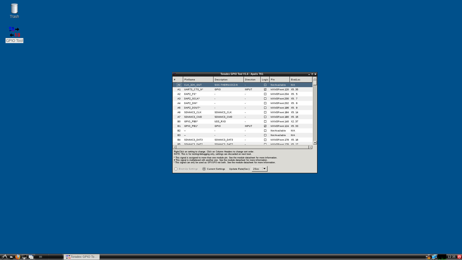
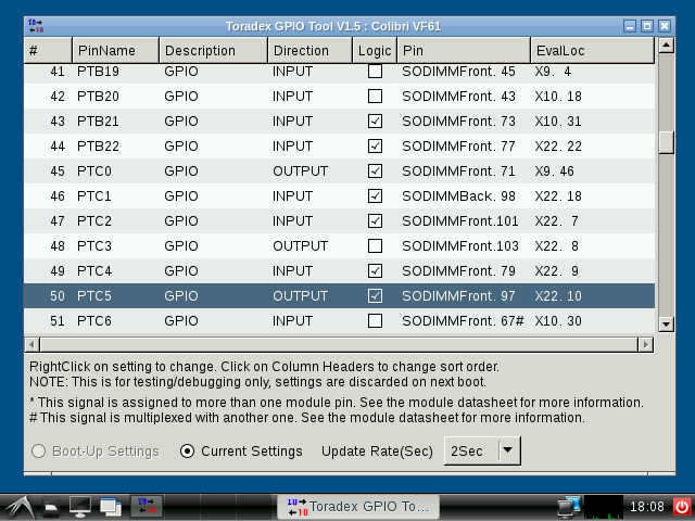
-

GPIO tool initial screen
Locate the pins 147 and 150 in the table. Right click the direction of each of them and configure pin 147 as INPUT and pin 150 as OUTPUT. See the changes reflected in the application.
-

Configuring MXM3 pin
Click the Logic checkbox of pin 150 and see the logic checkbox of pin 147 switch on/off.
The Linux sysfs interface provides an abstraction to access the GPIO, as well as many other hardware features, from the Linux user-space.
The pin has to be exported first, which guarantees that it is not being used by other kernel drivers nor allow other drivers to use it. It also has to be configured as input or output.
From the Linux terminal, export the pins 147 and 150:
echo 147 > /sys/class/gpio/export
echo 150 > /sys/class/gpio/export
Configure the pins as input and output, respectively:
echo "in" > /sys/class/gpio/gpio147/direction
echo "out" > /sys/class/gpio/gpio150/direction
Read the INPUT value as you toggle OUTPUT value:
echo 1 > /sys/class/gpio/gpio150/value
cat /sys/class/gpio/gpio147/value
echo 0 > /sys/class/gpio/gpio150/value
cat /sys/class/gpio/gpio147/value
The following steps are meant for readers that have the optional items listed in the beginning of this lesson. If you want to go through them, click the dropdown link below:
Steps 10 to 17
The steps below will use the following pins (Linux GPIO number) to toggle an LED and read the value of a switch:
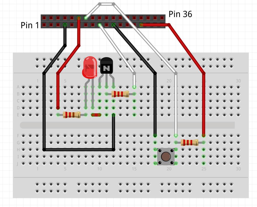
Use jumper wires to connect GPIO 150 to 2k2Ω Resistor , connect the resistor to transistor base pin, connect pin X27.12 (5V) from Ixora to 470Ω Resistor , connect the resistor to one LED and connect to transistor collector pin, connect the transistor emitter pin to pin X27.7 (GND) on Ixora Carrier Board. Use jumper wires to connect pin X27.29 (3,3V) to 2k2Ω Resistor , connect the resistor to one switch and to GPIO 147, and connect the node to pin X27.21 (GND) on Ixora Carrier Board.
-

Breadboard connection
-
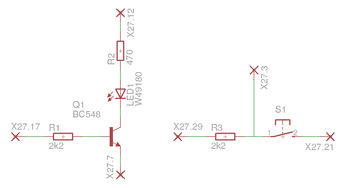
Schematic
Read the switch value as you toggle it:
cat /sys/class/gpio/gpio147/value
Note: If the module was rebooted the GPIO must be exported again as explained in Step 8.
Toggle the LED GPIO:
echo 1 > /sys/class/gpio/gpio150/value
echo 0 > /sys/class/gpio/gpio150/value
Note: If the module was rebooted the GPIO must be exported again as explained in Step 8.
There is a debug interface provided by the kernel debugfs for GPIO, which holds information about GPIO pins already reserved for drivers, as well as pin configuration and state. See the example below for the Apalis T30, and try it yourself:
root@apalis-t30:~# cat /sys/kernel/debug/gpio
GPIOs 0-255, tegra-gpio:
gpio-26 (THERMD_ALERT_N ) in hi
gpio-68 (RESET_MOCI_N ) out hi
gpio-77 (EN_+3.3_SDMMC3 ) out hi
gpio-111 (HDMI1_HPD ) in lo
gpio-128 (GPIO6 X1-11 ) out hi
gpio-129 (GPIO8 X1-15, FAN ) out hi
gpio-146 (GPIO1 X1-1 ) in lo
gpio-147 (GPIO2 X1-3 ) out hi
gpio-148 (GPIO3 X1-5 ) in lo
gpio-149 (GPIO4 X1-7 ) in lo
gpio-150 (GPIO5 X1-9 ) out hi
gpio-151 (PEX_PERST_N ) out hi
gpio-153 (VI_LevelShifter_DIR ) out lo
gpio-168 (TOUCH_PEN_INT ) in hi
gpio-169 (KEY_WAKEUP ) in hi
gpio-170 (BKL1_ON ) out hi
gpio-171 (sdhci_cd ) in hi
gpio-216 (LVDS: Single/Dual Ch) out lo
gpio-219 (LVDS: 18/24 Bit Mode) out hi
gpio-220 (LVDS: Output Enable ) out hi
gpio-221 (LVDS: Power Down ) out hi
gpio-222 (LVDS: Clock Polarity) out hi
gpio-223 (LVDS: Colour Mapping) out hi
gpio-225 (LVDS: Swing Mode ) out hi
gpio-226 (LVDS: DDRclk Disable) out hi
gpio-229 (sdhci_cd ) in hi
gpio-232 (SATA1_ACT_N ) out hi
gpio-233 (usb_host_vbus ) out hi
GPIOs 256-264, i2c/4-002d, tps6591x, can sleep:
gpio-262 (fixed_reg_en_hdmi ) out lo
See that the pins 147 and 150, configured as input and output in the previous steps, are correctly configured as in and out respectively.
Export, unexport, configure and toggle the GPIO pins as you read the debugfs information to see the changes.
Note: If you want additional pin configuration debug, explore the /sys/kernel/debug/tegra_pinmux/ directory.
Write a small C application that toggles the LED GPIO. A small source-code is given below for reference and you may copy-paste it to your previously configured Eclipse environment.
Warning: The source-codes provided in this guide are distributed under the 3-clause BSD license terms. See below:
License
Copyright (c) 2017, Toradex
All rights reserved.
Redistribution and use in source and binary forms, with or without
modification, are permitted provided that the following conditions are met:
* Redistributions of source code must retain the above copyright
notice, this list of conditions and the following disclaimer.
* Redistributions in binary form must reproduce the above copyright
notice, this list of conditions and the following disclaimer in the
documentation and/or other materials provided with the distribution.
* Neither the name of the Toradex nor the
names of its contributors may be used to endorse or promote products
derived from this software without specific prior written permission.
THIS SOFTWARE IS PROVIDED BY THE COPYRIGHT HOLDERS AND CONTRIBUTORS "AS IS" AND
ANY EXPRESS OR IMPLIED WARRANTIES, INCLUDING, BUT NOT LIMITED TO, THE IMPLIED
WARRANTIES OF MERCHANTABILITY AND FITNESS FOR A PARTICULAR PURPOSE ARE
DISCLAIMED. IN NO EVENT SHALL Toradex BE LIABLE FOR ANY
DIRECT, INDIRECT, INCIDENTAL, SPECIAL, EXEMPLARY, OR CONSEQUENTIAL DAMAGES
(INCLUDING, BUT NOT LIMITED TO, PROCUREMENT OF SUBSTITUTE GOODS OR SERVICES;
LOSS OF USE, DATA, OR PROFITS; OR BUSINESS INTERRUPTION) HOWEVER CAUSED AND
ON ANY THEORY OF LIABILITY, WHETHER IN CONTRACT, STRICT LIABILITY, OR TORT
(INCLUDING NEGLIGENCE OR OTHERWISE) ARISING IN ANY WAY OUT OF THE USE OF THIS
SOFTWARE, EVEN IF ADVISED OF THE POSSIBILITY OF SUCH DAMAGE.
Source code 1
#include <stdlib.h>
#include <fcntl.h>
#include <unistd.h>

int main(int argc, char *argv[]){
    int fd;

    // export GPIO
    fd = open("/sys/class/gpio/export", O_WRONLY);
    write(fd, "150", 3);
    close(fd);

    // Configure as output
    fd = open("/sys/class/gpio/gpio150/direction", O_WRONLY);
    write(fd, "out", 3);
    close(fd);

    // Blink GPIO once
    fd = open("/sys/class/gpio/gpio150/value", O_WRONLY | O_SYNC);
    write(fd, "0", 1);
    usleep(1000000);
    write(fd, "1", 1);
    close(fd);

    return EXIT_SUCCESS;
}
Write a small C application that reads the switch GPIO. A small source-code is given below for reference and you may copy-paste it to your previously configured Eclipse environment.
Source code 2
#include <stdio.h>
#include <stdlib.h>
#include <fcntl.h>
#include <unistd.h>

int main(int argc, char *argv[]){
    int fd;
    char value;

    // export GPIO
    fd = open("/sys/class/gpio/export", O_WRONLY);
    write(fd, "147", 3);
    close(fd);

    // configure as input
    fd = open("/sys/class/gpio/gpio147/direction", O_WRONLY);
    write(fd, "in", 2);
    close(fd);

    // read GPIO once
    fd = open("/sys/class/gpio/gpio147/value", O_RDONLY);
    read(fd, &value, 1); // read GPIO value
    printf("GPIO value: %c\n", value); // print GPIO value
    close(fd); //close value file

    return EXIT_SUCCESS;
}
The GPIO sysfs interface enables the use of interrupts from user space, as long as it is supported by the underlying hardware. Read the sysfs GPIO documentation, have a look at the poll system call and try to implement an application that handles the interrupt. Have a look at the source code below for reference:
Source code 3
#include <stdio.h>
#include <stdlib.h>
#include <fcntl.h>
#include <unistd.h>
#include <poll.h>

int main(int argc, char *argv[]){
    int fd;
    char value;
    struct pollfd poll_gpio;

    poll_gpio.events = POLLPRI;

    // export GPIO
    fd = open("/sys/class/gpio/export", O_WRONLY);
    write(fd, "147", 3);
    close(fd);

    // configure as input
    fd = open("/sys/class/gpio/gpio147/direction", O_WRONLY);
    write(fd, "in", 2);
    close(fd);

    // configure interrupt
    fd = open("/sys/class/gpio/gpio147/edge", O_WRONLY);
    write(fd, "rising", 6); // configure as rising edge
    close(fd);

    // open value file
    fd = open("/sys/class/gpio/gpio147/value", O_RDONLY);
    poll_gpio.fd = fd;

    poll(&poll_gpio, 1, -1); // discard first IRQ
    read(fd, &value, 1);

    // wait for interrupt
    while(1){
        poll(&poll_gpio, 1, -1);
        if((poll_gpio.revents & POLLPRI) == POLLPRI){
            lseek(fd, 0, SEEK_SET);
            read(fd, &value, 1);
            printf("Interrupt GPIO val: %c\n", value);
            break;
        }
    }

    close(fd); //close value file
    return EXIT_SUCCESS;
}
To prevent the main loop from blocking, run the GPIO IRQ handling in a separate thread. Try to implement it.
Improve the code from the previous steps to handle errors and add other functionality you want. The code below implements a frequency meter by measuring the elapsed time between GPIO interruptions:
Source code 4
#include <stdio.h>
#include <stdlib.h>
#include <fcntl.h>
#include <unistd.h>
#include <poll.h>
#include <time.h>
#include <string.h>
#include <errno.h>

// high priority or an error occured in SW
#define POLL_GPIO POLLPRI | POLLERR

#define TIMEOUT 10
#define SAMPLES 500

#define EXPORT_PATH      "/sys/class/gpio/export"
#define SW_VAL_PATH      "/sys/class/gpio/gpio147/value"
#define SW_INT_PATH      "/sys/class/gpio/gpio147/edge"
#define SW_DIR_PATH      "/sys/class/gpio/gpio147/direction"

int configure_pins();

const char *sw = "248"; // Linux GPIO representation

void close_fd(int);
int configure_pins();

int main(int argc, char *argv[]){
	int fd, fd_edge, fd_export, count, poll_ret;
	double period, cpu_time_used;
	char value;
	struct pollfd poll_gpio;
    time_t t0, t1;

    configure_pins();

    while(fd = open(SW_VAL_PATH, O_RDONLY) <= 0);
    printf("Opened SW value sucessfully\n");

    // file descriptor from SW is being polled
	poll_gpio.fd = fd;
    // poll events in GPIO
    poll_gpio.events = POLL_GPIO;

    read(fd, &value, 1);

    while(1){

        t0 = time(0);

        for(count = 0; count <  SAMPLES; count++){
            lseek(fd, 0, SEEK_SET);
            read(fd, &value, 1); // read GPIO value
            poll_ret = poll(&poll_gpio, 1, TIMEOUT*1000);

            if(!poll_ret){
                printf("Timeout\n");
                return 0;
            }

            else{

                if(poll_ret == -1){
                    perror("poll");
                    return EXIT_FAILURE;
                }

                if(poll_gpio.revents & POLLPRI){
                    lseek(fd, 0, SEEK_SET);
                    read(fd, &value, 1); // read GPIO value
                    //printf("GPIO changed state!\n");
                }
            }
        }

        t1 = time(0);

        period = difftime(t1, t0) * 1000;

        period /= SAMPLES; // divide by n samples
		printf("Period (ms): %f \n", period);

	}

    close(fd); //close value file

    return EXIT_SUCCESS;
}

void close_fd(int fd){
	// close file from file descriptor
    if(close(fd) < 0){
        perror("Warning: Unable to close file correctly");
    }
}

int configure_pins(){
    int fd_export, fd_edge, fd_input;

    /*******************EXPORT*******************/
    // open export file
	if((fd_export = open(EXPORT_PATH, O_WRONLY)) <= 0){
		perror("Unable to open export file\n");
		return EXIT_FAILURE;
	}else printf("Opened export file successfully\n");
    // export SW GPIO
    if(write(fd_export, sw, strlen(sw)) < 0){
		if(errno != EBUSY){ // does not end if pin is already exported
       		perror("Unable to export SW GPIO\n");
			close_fd(fd_export);
			return EXIT_FAILURE;
		}
		perror("Warning: Unable to export SW GPIO\n");
    } else printf("Exported SW successfully\n");

	// close export file
	close_fd(fd_export);


    /******************DIRECTION******************/
    // open direction file
    if(fd_input = open(SW_DIR_PATH, O_WRONLY) <=0){
        perror("Unable to open direction file for PIN 147\n");
        return EXIT_FAILURE;
    } else printf("Opened direction file successfully\n");
	if(write(fd_input, "in", 2) < 0){ // configure as input
        if(errno != EBUSY){
            perror("Unable to change direction from SW\n");
            close_fd(fd_input);
            return EXIT_FAILURE;
        }
        perror("Warning: unable to change direction from SW\n");
    }else printf("Changed direction from SW successfully\n");

    close_fd(fd_input); // close direction file


    /********************EDGE*********************/
    while(fd_edge = open(SW_INT_PATH, O_RDWR) <=0);
    printf("Opened edge file successfully\n");
    while(write(fd_edge, "rising", 6) < 0);
    printf("Changed edge from SW successfully\n");
    close_fd(fd_edge);

    return EXIT_SUCCESS;
}
This lesson only covers the basics of GPIO usage on Linux. Since there are other important topics that were not discussed, this FAQ section is meant as an information complement.
What is the sysfs interface
Quoting the Linux kernel documentation:
sysfs is a ram-based filesystem initially based on ramfs. It provides
a means to export kernel data structures, their attributes, and the
linkages between them to userspace.
See the kernel documentation for additional information:
sysfs
Should I always use the sysfs interface when I need to use a GPIO
Often there are kernel modules for dedicated purposes, which are preferred to implementing on your own. Examples of such are the control of LEDs, display backlight and power management.
In addition, there are hardware interfaces that may best suit your purposes, such as the PWM interface and other peripherals.
Browse this FAQ for reference regarding these alternatives.
Can I control backlight brightness using GPIO
All Toradex modules come configured to control a display backlight. For such purpose, one of the hardware PWM interfaces and a GPIO, as well as the Linux kernel backlight API, are employed.
The PWM interface is responsible for controlling the display brightness, and the GPIO for toggling it on/off.
For more details please consult the correspondent section of the GPIO article:
[Backlight (Linux)]http://developer.toradex.com/knowledge-base/backlight-(linux "Backlight (Linux)")
Is it possible to use a GPIO to shutdown the system
To use a GPIO as a power management input, you have to alter the device-tree and create a udev rule.
For more details please consult the correspondent section of the GPIO article:
Power Management Keys
Additionally, a GPIO can be used as an interrupt source to wake-up the system from a low-power state. The MXM3 4 is defined as the wake-up pin by default.
For more details please consult the Suspend/Resume article:
Suspend/Resume
Can I bypass sysfs to have direct access to GPIO
If there isn't a kernel driver that suits your needs, you can access GPIO from kernel space rather than user space, and use the gpio.h kernel library.
There are other ways to access GPIO registers directly either from user space (using mmap) or kernel space (using ioremap). Those are problematic since they bypass the kernel handling of the GPIO controllers and might lead to unexpected behavior.
What happens when a GPIO pin is unexported
The behavior is not well defined for every module, depending on the provided BSP. If this knowledge is really required, you might verify the kernel GPIO/pinctrl subsystem.