Attention: the Quickstart Guide for BSP 2.8, based on the Ångström distribution, is not being updated anymore. Depending on your SoM, you have different options:
Vybrid and Tegra: the information is provided as-is and still accurate, since newer Toradex BSPs are not ported to those SoMs. Just keep in mind that the Guides are not being maintained anymore, even if we find bugs or outdated instructions.
Apalis TK1 (all variants), Colibri iMX6ULL (all variants), Colibri iMX7S 256MB and Colibri iMX7D 512MB: these computer on modules are still regularly maintained in our BSPs and, to get started, you must check the software page Toradex BSP Layers and Reference Images for Yocto Project. Since Torizon is not supported, at the moment a Quickstart Guide is not available.
All other i.MX-based SoMs: you have two options to get started with embedded Linux: the first is to follow the Quickstart Guide for Torizon, which provides the greatest out-of-the-box experience, or if you choose to use Yocto, check the software page Toradex BSP Layers and Reference Images for Yocto Project.
In this lesson, you will learn the basics of GPIO usage on Linux, being able to read or write to a GPIO pin from command-line, as well as by developing a minimal C application.
In this lesson you will:
The information provided in this guide is based in Toradex's knowledge base article GPIO (Linux), as well as other knowledge sources such as kernel documentation and the Linux man-pages project.
The Apalis Evaluation Board already has buttons and LEDs available for debugging purposes, therefore only jumper wires are required.
To find out which GPIO number to use in the Linux sysfs interface, you have to know the correspondence between available pins in the carrier board, number of the correspondent pins on the MXM3 connector of the Apalis computer on module and number of the pins on Linux.
Download or open in a web browser the Apalis Evaluation Board and the Apalis TK1 datasheets from the respective products pages of the developer website:
Apalis Evaluation Board datasheet
For this introduction guide, some pins configured by default as GPIO in the Toradex BSP were chosen. The choice of pins was made based on their availability on all the carrier boards covered by the getting-started guide. This module will not go through the configuration of other pins as GPIO, although it is possible.
First of all, you need to find the correspondence between the MXM3 and the connectors exposed for the developer on the Apalis Evaluation Board. Consult the Apalis Evaluation Board datasheet and fill the table below based in the example provided:
Note: The notation CONNECTOR.PIN will be employed in this lesson, e.g. X12.5 means pin 5 of the X12 connector.
| Apalis Evaluation Board (connector.pin) | MXM3 pins |
|---|---|
| X3.9 | 3 |
| 11 | |
| 13 |
Have a look at the table available in the "TK1 Functions List" chapter of the Apalis TK1 datasheet. It provides a list of most of the Apalis pins available on the MXM3 connector.
The MXM3 pins we are interested at are connected to the TK1 SoC and have names defined by the TK1 Ball Name function. Each pin is multiplexed to have a specific function - among them GPIO, therefore the GPIO function is the column that we are interested at.
Having a look at the GPIO Alphanumeric to GPIO Numeric Assignment article, the correspondence between TK1 GPIO name and the Linux numeric representation of the GPIO pins is provided as a table. To find it from the GPIO column it is possible to use the formula below:
GPIO3_P[x].0[y]Linux numeric representation = 8 X (x - 'A') + yOn the formula above, the x is a character, you need to find the number corresponding to the alphabetic letter, as example A=1, B=2, C=3, AA=27.
Below is an example of how to use the formula, the number inside parentheses are the number corresponding to the alphabetic letter:
GPIO3_PD.03 = 8 X (D(4) - A(1)) + 3 = 27Either by consulting the table from the article pointed above or calculating it, the previous table with the correspondence between Ixora Carrier Board pins and MXM3 pins can be extended to have the TK1 GPIO name, formed by GPIO controller, always GPIO3, plus pin at SoC level, as the example above PD.03, and the Linux numeric representation. Fill the table below based in the example provided:
| Apalis Evaluation Board (connector.pin) | MXM3 pins | TK1 GPIO name | Linux GPIO number |
|---|---|---|---|
| X3.9 | 3 | GPIO3_PFF.00 | 248 |
| X3.6 | 11 | ||
| X3.5 | 13 |
Choose two of the GPIO pins from the list above to toggle an LED and read the value of a switch. This lesson will use the following pins (Linux GPIO number):
Use jumper wires to connect GPIO 248 to the slide switch SW4 on the connector X34.3, and GPIO 237 to the LED1 on the connector X34.4.
Note: For more informations about pins schematic, please access the Apalis Evaluation Board schematics here.
Note: You may use any other of the LEDs/switches available. Please refer to the section 3.13.2.1.1 LED/Switches (X34) of the Apalis Evaluation Board datasheet.

Connecting the MXM3 pins to the LED and switch
The Toradex Linux pre-built image comes with a tool named Toradex GPIO tool meant for debugging pins configuration. It can also be used to determine the correspondences found in the previous step. We will use it to test the hardware connections.
Note: You need a display and a mouse connected to the system in order to use the GPIO tool. Please go to the beginning of the getting-started guide for more information about assembling the peripherals.
Run the GPIO tool from the target Linux desktop:
Starting the GPIO tool
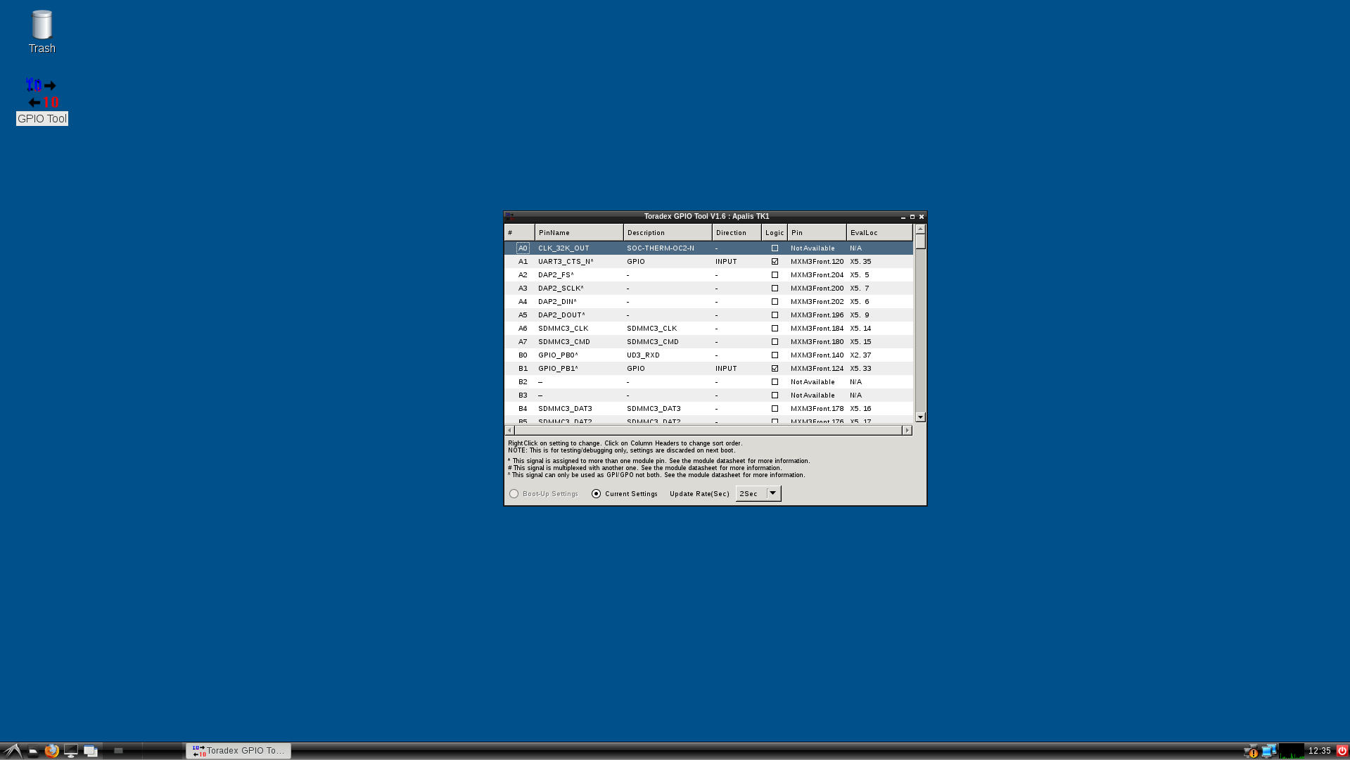
GPIO tool initial screen
Locate the pins 248 and 237 in the table. Right click the direction of each of them and configure pin 248 as INPUT and pin 237 as OUTPUT. See the changes reflected in the application.

Configuring MXM3 pin
Toggle the switch SW4 and see the Logic checkbox of the pin 248 change its state. Click the Logic checkbox of pin 237 and see the LED switch on/off.

LED toggled from GPIO tool
The Linux sysfs interface provides an abstraction to access the GPIO, as well as many other hardware features, from the Linux user-space.
The pin has to be exported first, which guarantees that it is not being used by other kernel drivers nor allow other drivers to use it. It also has to be configured as input or output.
From the Linux terminal, export the pins 248 and 237:
echo 248 > /sys/class/gpio/exportecho 237 > /sys/class/gpio/exportConfigure the pins as input and output, respectively:
echo "in" > /sys/class/gpio/gpio248/directionecho "out" > /sys/class/gpio/gpio237/directionRead the switch value as you toggle it:
cat /sys/class/gpio/gpio248/valueToggle the LED GPIO:
echo 1 > /sys/class/gpio/gpio237/valueecho 0 > /sys/class/gpio/gpio237/valueThere is a debug interface provided by the kernel debugfs for GPIO, which holds information about GPIO pins already reserved for drivers, as well as pin configuration and state. See the example below for the Apalis TK1, and try it yourself:
root@apalis-tk1:~# cat /sys/kernel/debug/gpioGPIOs 0-255, platform/6000d000.gpio, tegra-gpio:gpio-63 (+V1.05_AVDD_HDMI_PLL) out logpio-70 (temp_alert ) in higpio-108 (VCC_USBO1 ) out logpio-109 (VCC_USBH(2A|2C|2D|3|) out higpio-111 (hdmi_hpd ) in higpio-117 (WOL_GPIO ) in higpio-146 (LAN_RESET_N ) out higpio-164 (RESET_MOCI_N ) out higpio-170 (sdhci_cd ) in logpio-171 (sdhci_cd ) in higpio-221 (BKL1_ON ) out higpio-233 (PEX_PERST_N ) out higpio-235 (WAKE1_MICO ) in higpio-237 (sysfs ) out logpio-248 (sysfs ) in loGPIOs 1016-1023, platform/as3722-pinctrl, as3722-gpio, can sleep:gpio-1018 (+V3.3 ) out hiSee that the pins 248 and 237, configured as input and output in the previous steps, are the only ones taken by sysfs and are correctly configured as in and out respectively.
Export, unexport, configure and toggle the GPIO pins as you read the debugfs information to see the changes.
Note: If you want additional pin configuration debug, explore the /sys/kernel/debug/pinctrl/ directory.
Write a small C application that toggles the LED GPIO. A small source-code is given below for reference and you may copy-paste it to your previously configured Eclipse environment.
Warning: The source-codes provided in this guide are distributed under the 3-clause BSD license terms. See below:
Write a small C application that reads the switch GPIO. A small source-code is given below for reference and you may copy-paste it to your previously configured Eclipse environment.
The GPIO sysfs interface enables the use of interrupts from user space, as long as it is supported by the underlying hardware. Read the sysfs GPIO documentation, have a look at the poll system call and try to implement an application that handles the interrupt. Have a look at the source code below for reference:
To prevent the main loop from blocking, run the GPIO IRQ handling in a separate thread. Try to implement it.
Improve the code from the previous steps to handle errors and add other functionality you want. The code below implements a frequency meter by measuring the elapsed time between GPIO interruptions:
This lesson only covers the basics of GPIO usage on Linux. Since there are other important topics that were not discussed, this FAQ section is meant as an information complement.
