Attention: the Quickstart Guide for BSP 2.8, based on the Ångström distribution, is not being updated anymore. Depending on your SoM, you have different options:
Vybrid and Tegra: the information is provided as-is and still accurate, since newer Toradex BSPs are not ported to those SoMs. Just keep in mind that the Guides are not being maintained anymore, even if we find bugs or outdated instructions.
Apalis TK1 (all variants), Colibri iMX6ULL (all variants), Colibri iMX7S 256MB and Colibri iMX7D 512MB: these computer on modules are still regularly maintained in our BSPs and, to get started, you must check the software page Toradex BSP Layers and Reference Images for Yocto Project. Since Torizon is not supported, at the moment a Quickstart Guide is not available.
All other i.MX-based SoMs: you have two options to get started with embedded Linux: the first is to follow the Quickstart Guide for Torizon, which provides the greatest out-of-the-box experience, or if you choose to use Yocto, check the software page Toradex BSP Layers and Reference Images for Yocto Project.
In this first lesson you will go through the process of unboxing your computer on module and carrier board and assembling the hardware.

Colibri iMX6ULL Eval Board Setup GIF
A block diagram of the system setup and its connections is presented below for reference.
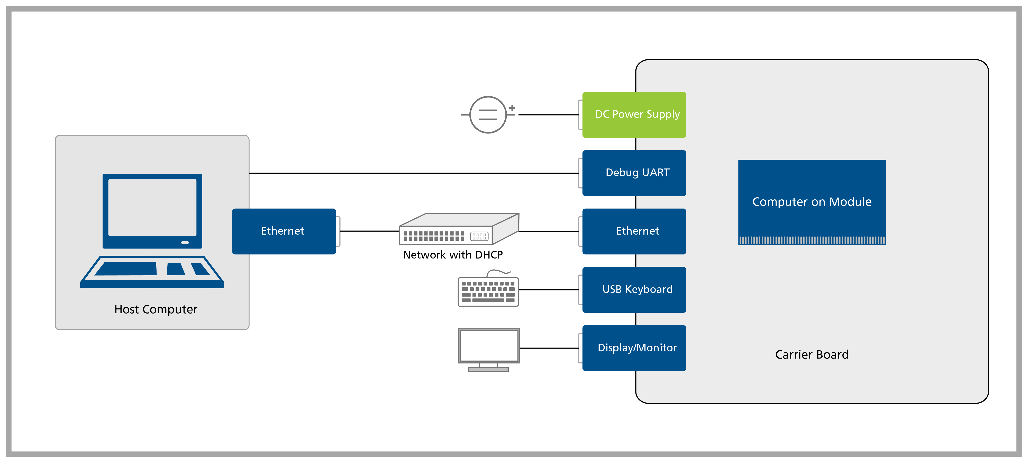
System setup block diagram
The following table lists the items required:
| List of items required |
|---|
| VGA display/monitor |
| Accessory kit : |
| -12V 30W power supply |
| -USB Type-B to Type-A cable |
| -Ethernet cable |
| USB keyboard and mouse |
| 2.4GHz SMA antenna |
| SMA to U.FL cable |
Remove the Evaluation Board and the Colibri Computer on Module from the blisters.
Unpack the SMA antenna and the SMA to U.FL cable.
Connect the SMA antenna to the SMA to U.FL cable as shown in the picture below:
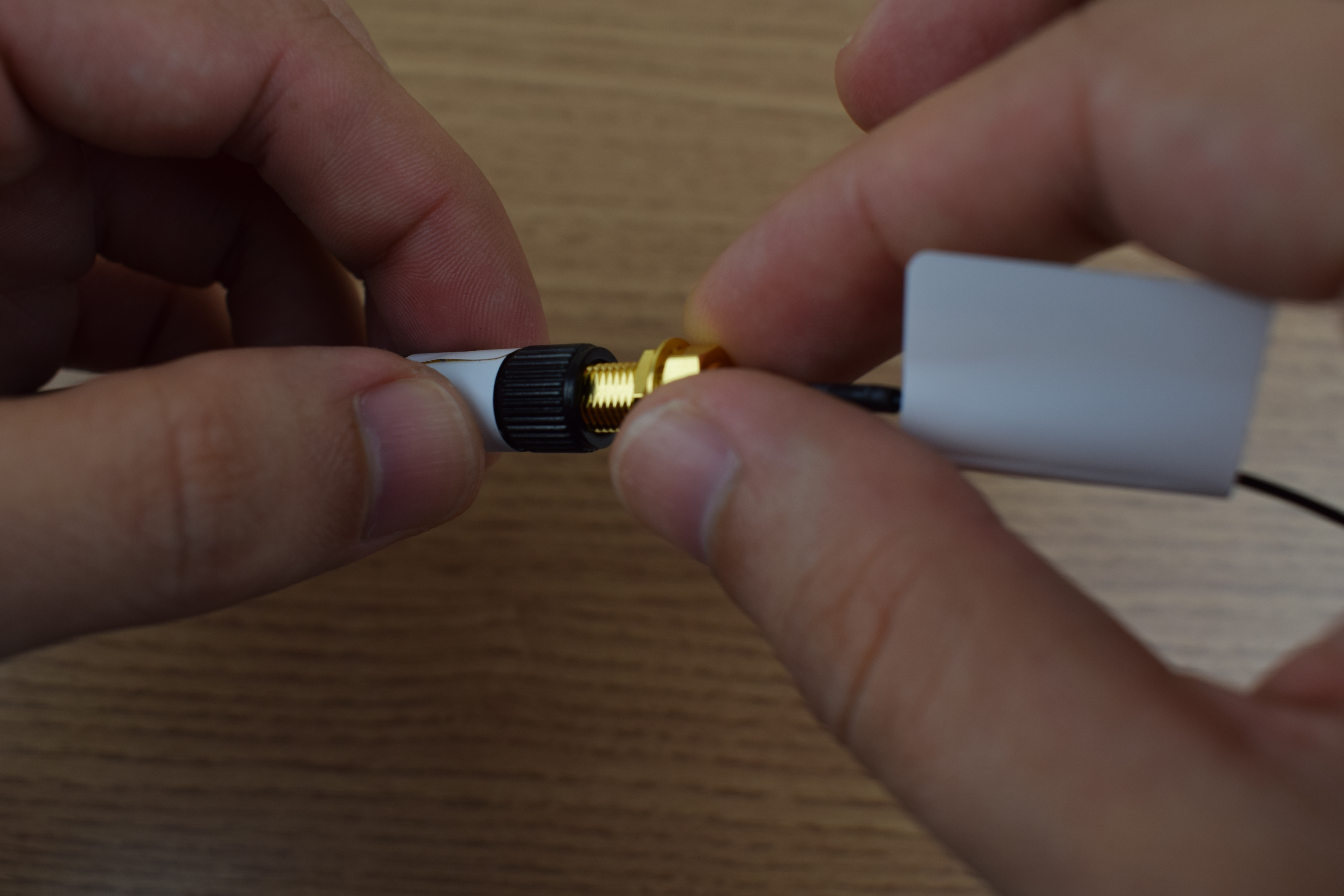
Connecting SMA antenna to SMA to U.FL adapter cable
Connect the antenna to the U.FL connector on the Colibri iMX6ULL module as following:

Connected U.FL antenna
Insert the computer on module into the X1 connector of the Evaluation Board as tight as possible, with the module inclined ~30 to 45 degree in relation to the carrier board.

Connecting the computer on module to the Colibri Evaluation Board
Warning: Make sure that the module is well connected to the board. The image below has some checkpoints highlighted.
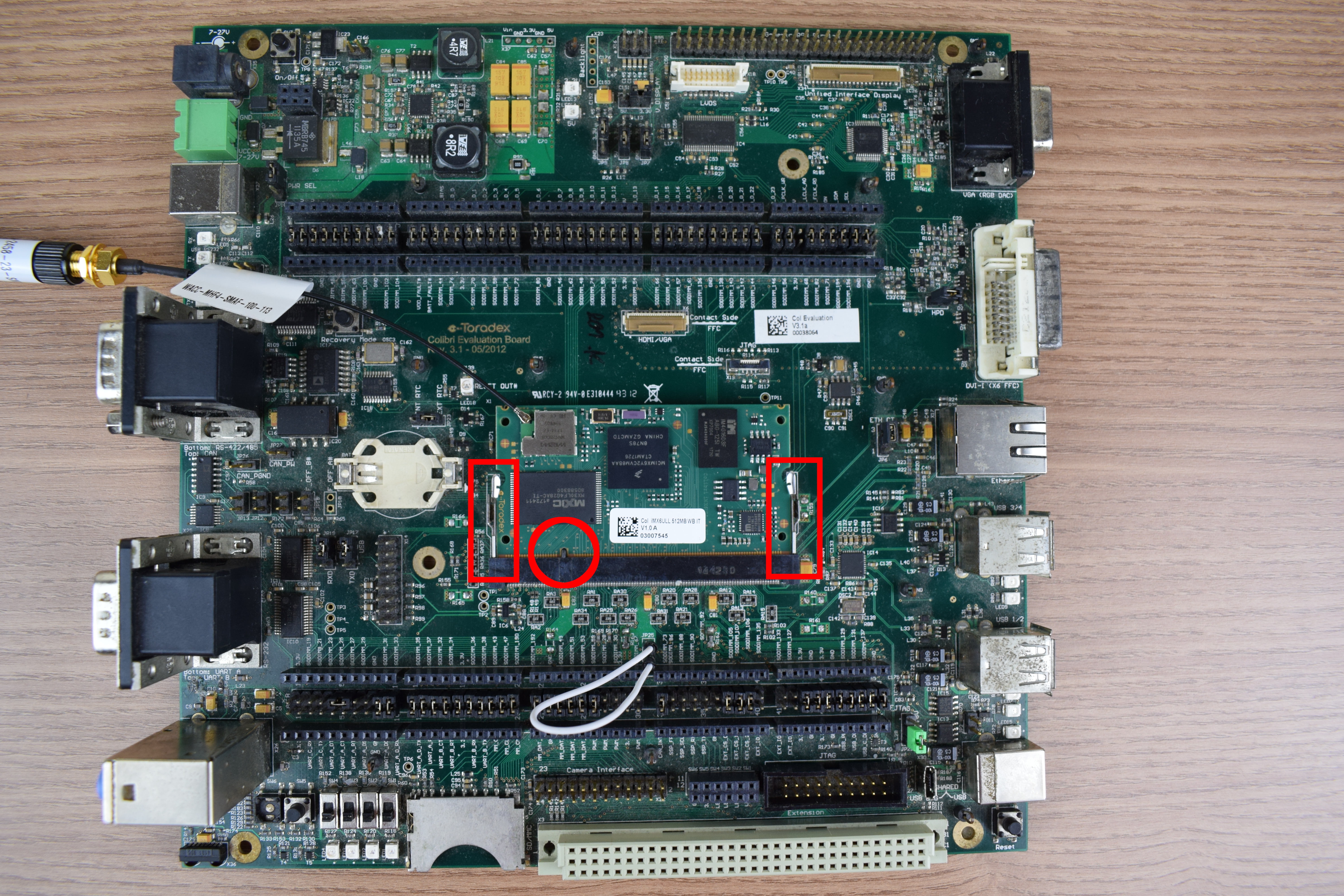
Computer on module connected to the Colibri Evaluation Board
Attention: Double check that your power supply is within the Evaluation Board limits (7-27V) and that the polarity is not inverted. Also, make sure that the current capability of the power supply is enough, or the system may shut down unexpectedly. For evaluation purposes, a 12V 2A power supply is recommended.

VGA, Ethernet, USB keyboard, power supply and USB Type-B to Type-A cable connected to the Evaluation Board
Make sure that the jumpers JP19 and JP17 are set to USB mode as shown in the image below, once we will use UART A via the USB Type-B connector X27.

Jumpers JP17 and JP19 - USB mode
