In this first lesson, you will go through the process of unboxing your computer on module and carrier board and assemble all the hardware:

Assembling the hardware
A block diagram of the system setup and its connections is presented below for reference.
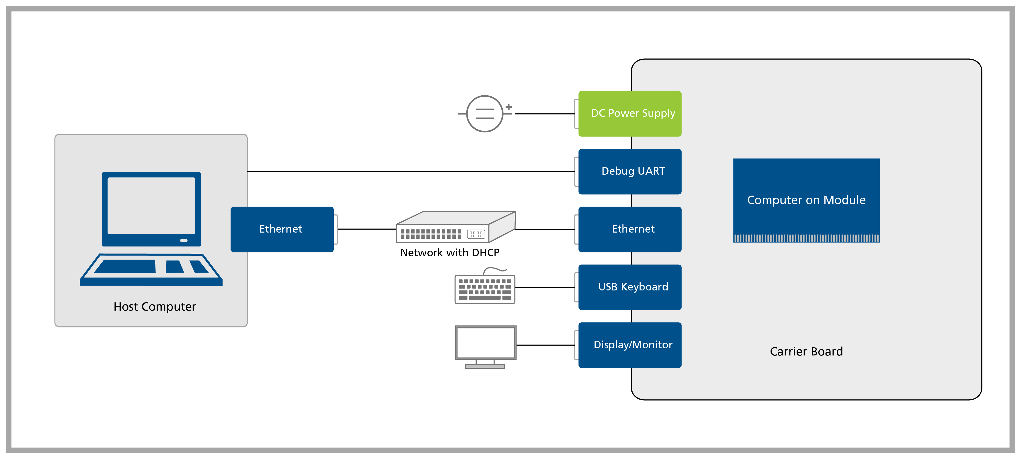
System setup block diagram
| List of items required |
|---|
| HDMI display/monitor |
| Accessory kit : |
| - 12V 30W power supply |
| - USB-Serial converter |
| - IDC to DB9 adapter cable |
| - Ethernet cable |
| - USB keyboard and mouse |
| Wi-Fi Cable and Antenna |
A headless setup is possible, though in the Quickstart Guide we will always assume that you have a recommended display attached to the carrier board. If you proceed without a display, skip the lessons that make use of it at your own discretion. As an option, you can follow the Torizon Documentation - just be aware you will not find a walkthrough as thorough as this guide.
Note: Carefully read this module's cover page clicking on "Module 1: Unboxing and Bring-up" on the left menu bar before starting this lesson.
Connect a compatible Wi-Fi Cable and Antenna, the following GIF illustrates what you need to do:

Antenna setup GIF
Note: Make sure to connect on the main slot, just like to the photo:

Main antenna slot
Remove the Evaluation Board and the Apalis Computer on Module from the blisters. Insert the computer on module into the X1 connector of the Evaluation Board as tight as possible, with the module inclined ~30 to 45 degrees in relation to the carrier board.
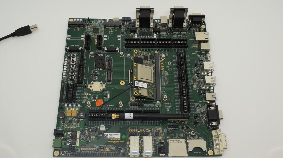
Connecting the computer on module to the Apalis Evaluation Board
Warning: Make sure that the computer on the module is well connected to the board. The image below has some checkpoints highlighted.

Computer on module connected to the Apalis Evaluation Board
Connect a DVI-D monitor to X11 and an Ethernet cable to X12 on the Evaluation Board. Also connect a USB keyboard to X53 or X54, a 12V power supply to the barrel jack X17 or use a 7-27 V power supply to X15. Finally, plug the USB Type-B to Type-A cable to X29. Make sure that the jumpers X39 and X40 are short-circuited in the DVI position, i.e. middle pins.
Attention: Double check that your power supply is within the Evaluation Board limits (7-27V to X15 connector or 12V to X17 connector) and that the polarity is not inverted. Also, make sure that the current capability of the power supply is enough, or the system may shut down unexpectedly. For evaluation purposes, a 12V 2A power supply is recommended.
Note: In the image below, the Apalis Heatsink is attached to the system. It is not mandatory for this getting-started guide, but keep in mind that excessive heat may reduce system performance. More information about the Apalis Heatsink is available here.
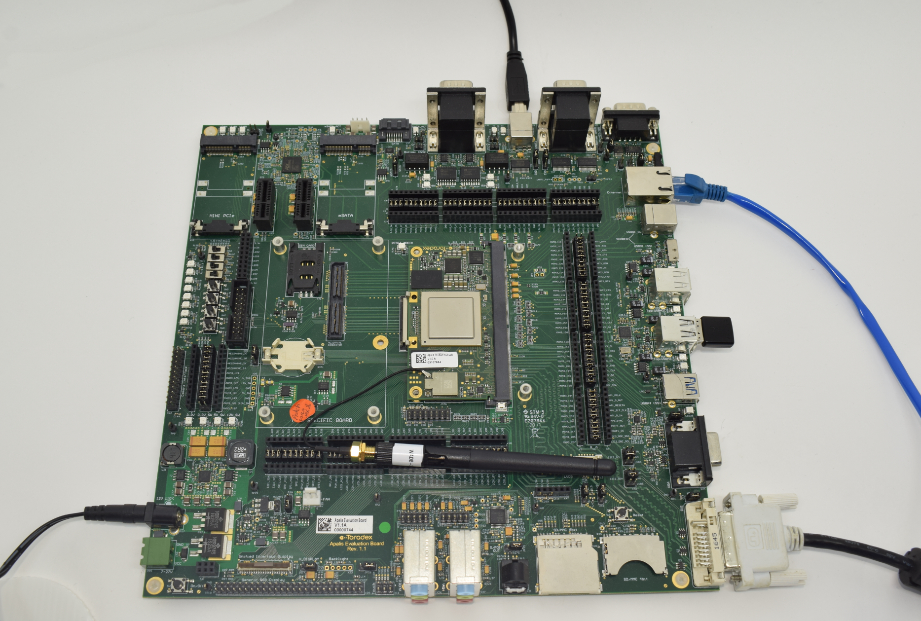
DVI-D, Ethernet, USB keyboard, power supply and USB Type-B to Type-A cable connected to the Evaluation Board
Make sure that the jumpers JP10 and JP12 are set to USB mode as shown in the image below, once we will use UART-1 via the USB Type-B connector X29.

Jumpers JP10 and JP12 - USB mode
Screw the heatsink to the carrier board and connect the fan on its top:

Heatsink connected to the carrier board
